General clamp for cavity milling in thin cover plate

A thin cover plate milling and fixture technology, applied in the field of structural parts processing, can solve the problem of difficult clamping, and achieve the effects of high work efficiency, novel structure and saving clamping time.

Active Publication Date: 2018-06-12
CETC CHIPS TECH GRP CO LTD
View PDF6 Cites 1 Cited by
  • Summary
  • Abstract
  • Description
  • Claims
  • Application Information

AI Technical Summary

Problems solved by technology

[0004] In view of this, the object of the present invention is to provide a time-saving, labor-saving and high-efficiency universal clamp for thin cover plate milling cavity, so as to solve the problem that the thin cover plate is difficult to clamp when milling the cavity on the machining center

Method used


Image

  • General clamp for cavity milling in thin cover plate
  • General clamp for cavity milling in thin cover plate
  • General clamp for cavity milling in thin cover plate

Examples


Embodiment Construction

[0033] Embodiments of the present invention are described below through specific examples, and those skilled in the art can easily understand other advantages and effects of the present invention from the content disclosed in this specification. The present invention can also be implemented or applied through other different specific implementation modes, and various modifications or changes can be made to the details in this specification based on different viewpoints and applications without departing from the spirit of the present invention. It should be noted that the diagrams provided in the following embodiments are only schematically illustrating the basic concept of the present invention, and the following embodiments and the features in the embodiments can be combined with each other in the case of no conflict.

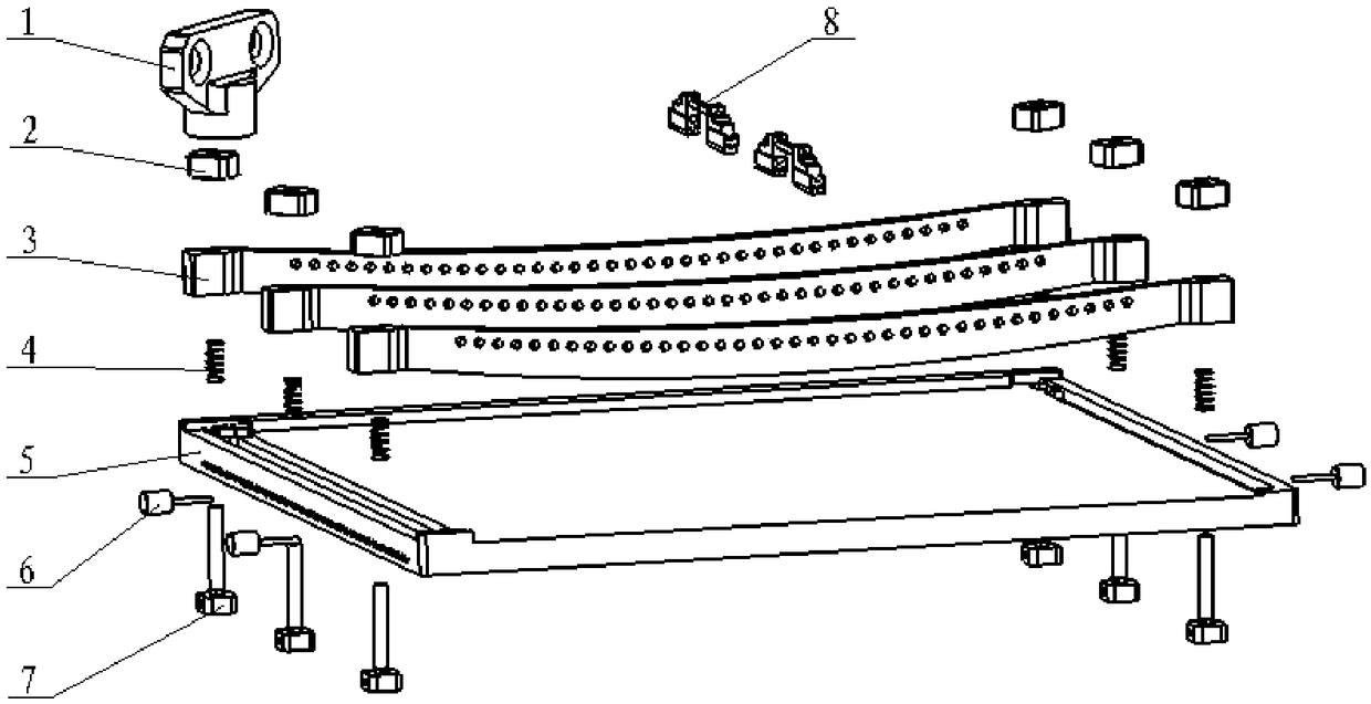
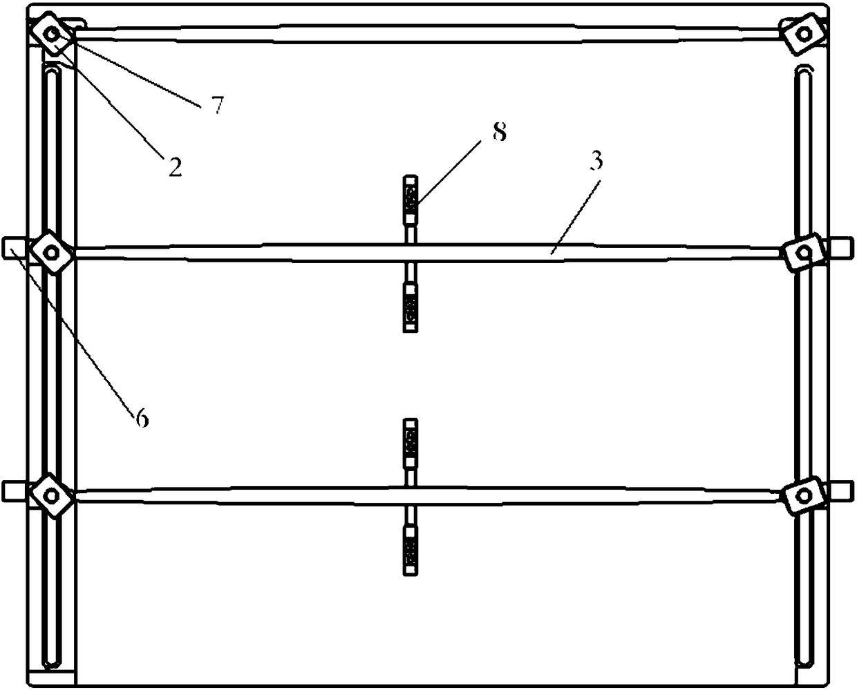
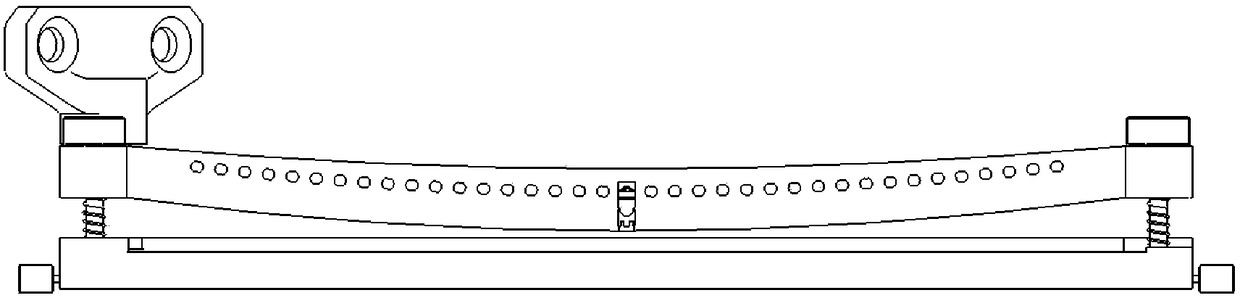
[0034] see Figure 1-9 , the component numbers in the accompanying drawings respectively represent: knob handle 1, rectangular nut 2, arc fish-belly beam 3, ...


PUM


Abstract

The invention discloses a general clamp for cavity milling in a thin cover plate, and relates to the field of machining of structural parts. The general clamp for cavity milling in the thin cover plate comprises a positioning base board and a movable compression module; the positioning base board comprises working base face on the upper surface and two strip-shaped through grooves in the two sidesof the length direction separately; the strip-shaped through grooves extend in the width direction and are through in the thickness direction; the movable compression module comprises at least two transverse compression devices composed of transverse pressing bars and locking mechanisms; and the transverse pressing bars make the thin cover plate abut against the working base face through the locking mechanisms with the two ends locked with the strip-shaped through grooves. The general clamp for cavity milling in the thin cover plate mainly solves the problems that clamping difficulty is largeand efficiency is low when a cavity is milled in the thin cover plate on a machining center.

Description

technical field [0001] The invention belongs to the technical field of structural parts processing, and relates to a machining fixture, in particular to a universal fixture for milling cavity of a thin cover plate. Background technique [0002] Modern military and civilian electronic equipment, especially airborne, spaceborne, missile-borne and vehicle-mounted radar and communication systems, are developing towards miniaturization and light weight. In order to meet the needs of light weight and miniaturization of electronic products, weight and external dimensions have become rigid indicators for evaluating products. Under the premise of satisfying the rigidity and strength of the overall structure, there are more and more structural parts of thin-plate electronic equipment. A set of shells generally includes a shell and two upper and lower thin cover plates covering the surface of the shell. The appearance and size of the thin cover plate are required to be high, and ther...

Claims


Application Information

Patent Timeline
Patent Type & Authority Applications(China)
IPC IPC(8): B23Q3/06
CPCB23Q3/065B23Q2703/10
Inventor 胡年孙江德风魏忠刘著祥龙震汪广扩文明刘斌梁红兵张英王发立
Owner CETC CHIPS TECH GRP CO LTD
Why Eureka
Try Eureka