Cloth dyeing machine with symmetrical double spiral cloth grooves

A double helix, symmetrical technology, applied in the field of dyeing machines, can solve the problems of difficult assembly of the helix, inconvenient operation, uneven pressure, etc., and achieve the effect of expanding the efficiency of the equipment

Active Publication Date: 2018-06-12
温必新
View PDF5 Cites 4 Cited by
  • Summary
  • Abstract
  • Description
  • Claims
  • Application Information

AI Technical Summary

Problems solved by technology

[0005] However, according to the investigation, the spiral body in this case is not easy to assemble in the cloth storage tank, and the cloth storage tank is a basket-shaped body. During maintenance, a crane or crane must be used to hang it from above, which is inconvenient to use; moreover, a cloth storage tank must Correspondingly, there is one cloth entr

Method used


Image

  • Cloth dyeing machine with symmetrical double spiral cloth grooves
  • Cloth dyeing machine with symmetrical double spiral cloth grooves
  • Cloth dyeing machine with symmetrical double spiral cloth grooves

Examples


Example Embodiment

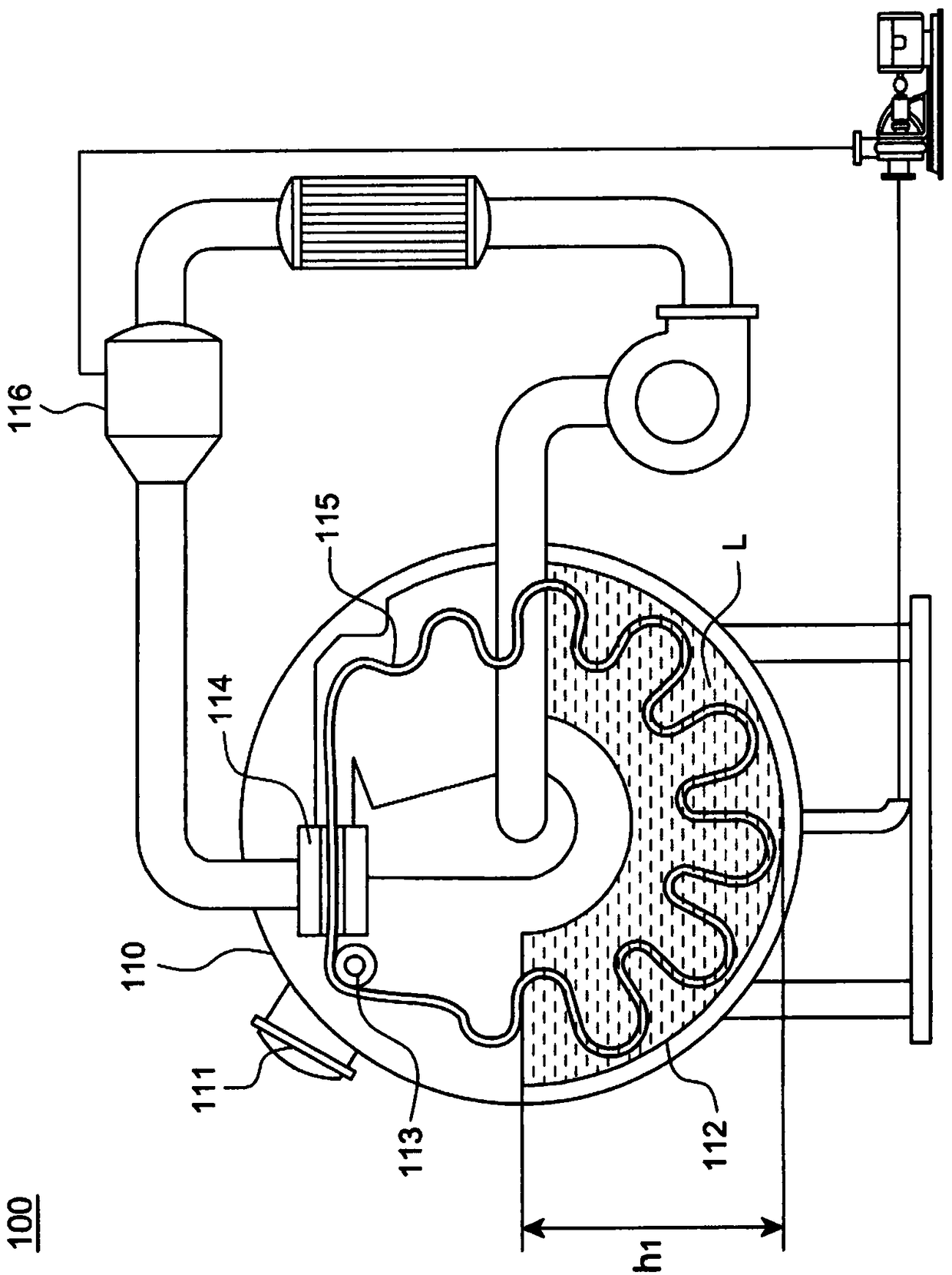
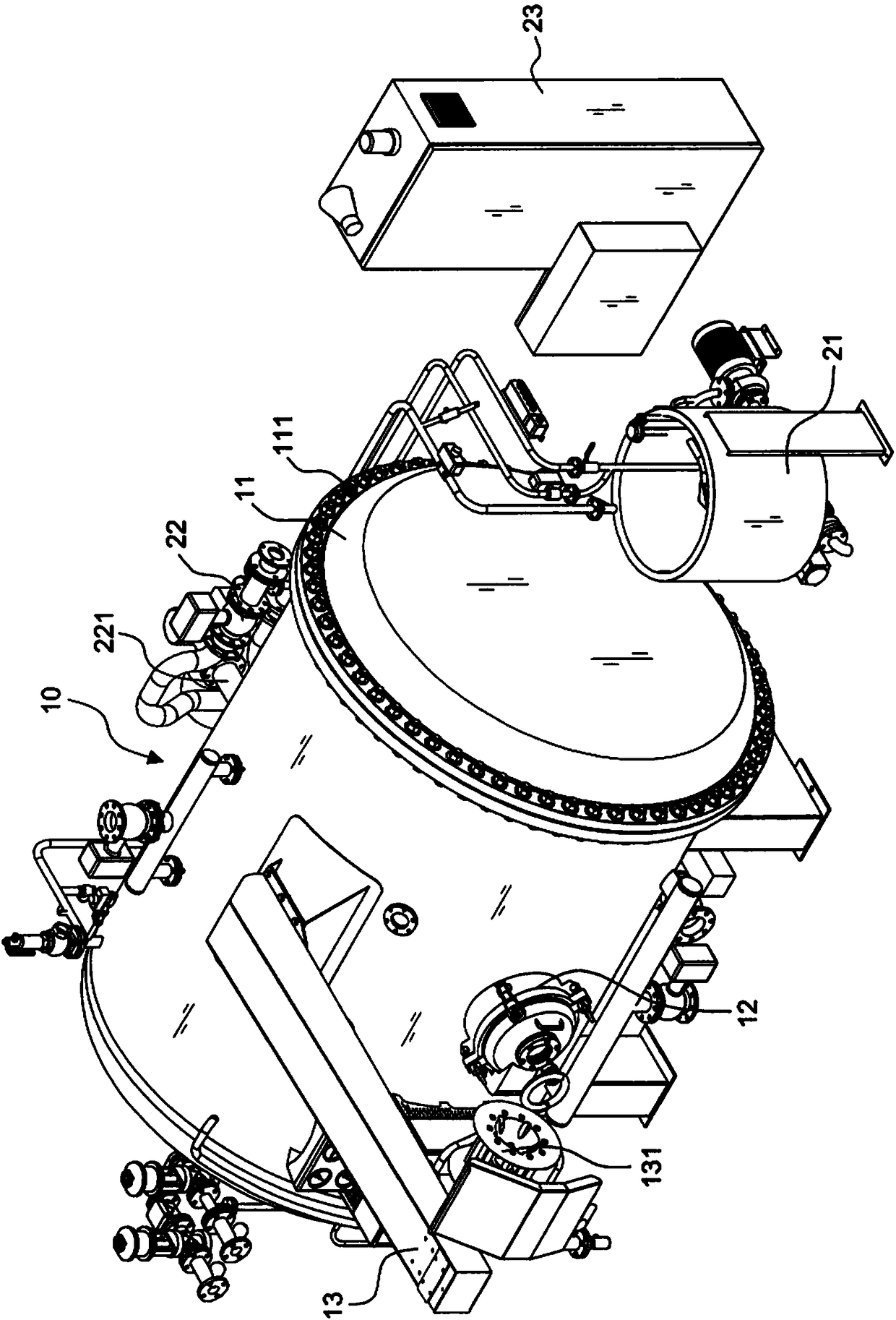
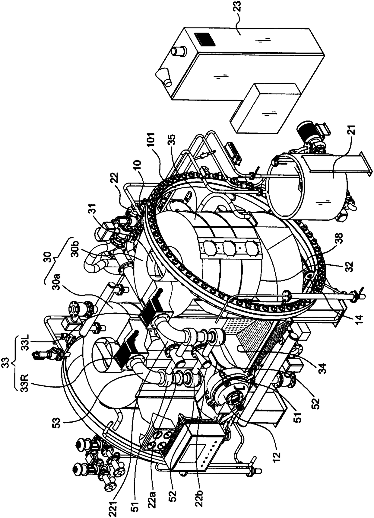
[0081] First, see Figure 2 to Figure 3C Shown is the appearance structure of the cloth dyeing machine in the present invention, including: a body 10 for accommodating cloth and dye solution for dyeing, the front side of the body 10 has a cloth inlet 12, and A cloth guide 13 placed above the cloth inlet 12, and the outer end of the cloth guide 13 may be provided with a runner 131 or Picture 10 The two wheels 131 shown can be implemented to drive the cloth to be smoothly inserted and taken out from the cloth inlet 12; in addition, on the outside of the carcass 10, a dye injection mechanism 21 and a dyeing The liquid input mechanism 22, the dye liquid input mechanism 22 has an outlet pipe 221, an inlet pipe 222 and a pump 223 ( Figure 5 Show); and apply a control mechanism 23 and heat exchanger 40 (such as Figure 3C (Shown), under the conditions of the fabric dyeing process that requires heating or cooling, the dye liquor is circulated in the carcass 10 to impregnate the cloth; ...


PUM


Abstract

The invention provides a cloth dyeing machine with symmetrical double spiral cloth grooves. A machine body is provided with a cloth feeding hole, and the two spiral cloth grooves are formed in parallel in the machine body and correspondingly arranged on the two sides of the cloth feeding hole. The cloth dyeing machine is provided with cloth guide pipes, spiral-body cloth sliding plates and a receiving groove; the two cloth guide pipes are close to the adjacent sides, face the front and are opposite right and left and symmetrical, after the spiral-body cloth sliding plates are connected with the cloth guide pipes respectively, cloth moves spirally from up to bottom in the opposite direction, and the cloth is soaked and dyed in the spiral cloth grooves in cycle; the two spiral cloth groovesare opposite and symmetrically arranged in the machine body in parallel, the cloth accommodating space is expanded, the dyed cloth quality and the production efficiency are improved, the low bath ratio can be reached, and energy is saved.

Description

technical field [0001] The invention relates to a cloth dyeing machine, especially a cloth dyeing machine without a cloth wheel device in the body, and two helical cloth grooves are arranged symmetrically and side by side in a double helical cloth groove of the body. Background technique [0002] Such as figure 1 Shown is a schematic diagram of an existing O-shaped body dyeing machine 100, which includes: a body 110, which is O-shaped, and has a cloth inlet 111 for inserting and taking out cloth 115; a U-shaped storage The cloth groove 112 is combined in the body 110; a cloth wheel 113 is arranged above the U-shaped cloth storage groove 112; a nozzle 114 is arranged at the rear of the cloth wheel 113, and the cloth wheel 113 will The cloth 115 of the U-shaped cloth storage tank 112 is lifted and introduced into the nozzle 114; and a dye liquid input device 116, which inputs the dye liquid into the nozzle 114, so that the cloth 115 is sequentially circulated and dyed in the ...

Claims


Application Information

Patent Timeline
IPC IPC(8): D06B23/04D06B23/20
CPCD06B23/04D06B23/20
Inventor 温必新
Owner 温必新
Why Eureka
Try Eureka