Pneumatic ice and snow removing machine

An ice and snow machine, pneumatic technology, applied in the direction of snow cleaning, construction, cleaning methods, etc., can solve the problem of low degree of ice and snow treatment, and achieve the effect of not easy to waste resources, rational use, and low practicability

Inactive Publication Date: 2018-06-12
狄程楠
View PDF0 Cites 1 Cited by
  • Summary
  • Abstract
  • Description
  • Claims
  • Application Information

AI Technical Summary

Problems solved by technology

[0002] As everyone knows, a pneumatic snow removal machine is a device that compresses the air to generate kinetic energy to drive tools to remove snow on the road to ensure that pedestrians and vehicles can pass safely, and is widely used in daily life; existing The pneumatic snow removal machine includes a base plate, a fan, a compressor, a heating chamber, an electric heating rod, a driving gear, a passive gear, multiple sets of shovel blades, two sets of first fixing frames and two sets of second fixing frames, and two sets of first fixing frames and two sets of second fixing frames are respectively installed on the top and bottom ends of the bottom plate, and a first rotating shaft and a second rotating shaft are respectively arranged between the two groups of first fixing frames and the two groups of second fixing frames, so The driving gear and the second gear are sleeved on the first rotating shaft and the second rotating shaft respectively, multiple groups of pneumatic plates are arranged on the side wall of the driving gear, the fan is installed on the top of the bottom plate, and the compressor is located at the top of the fan At the

Method used


Image

  • Pneumatic ice and snow removing machine
  • Pneumatic ice and snow removing machine
  • Pneumatic ice and snow removing machine

Examples


Example Embodiment

[0016] The specific embodiments of the present invention will be described in further detail below in conjunction with the drawings and embodiments. The following examples are used to illustrate the present invention, but not to limit the scope of the present invention.

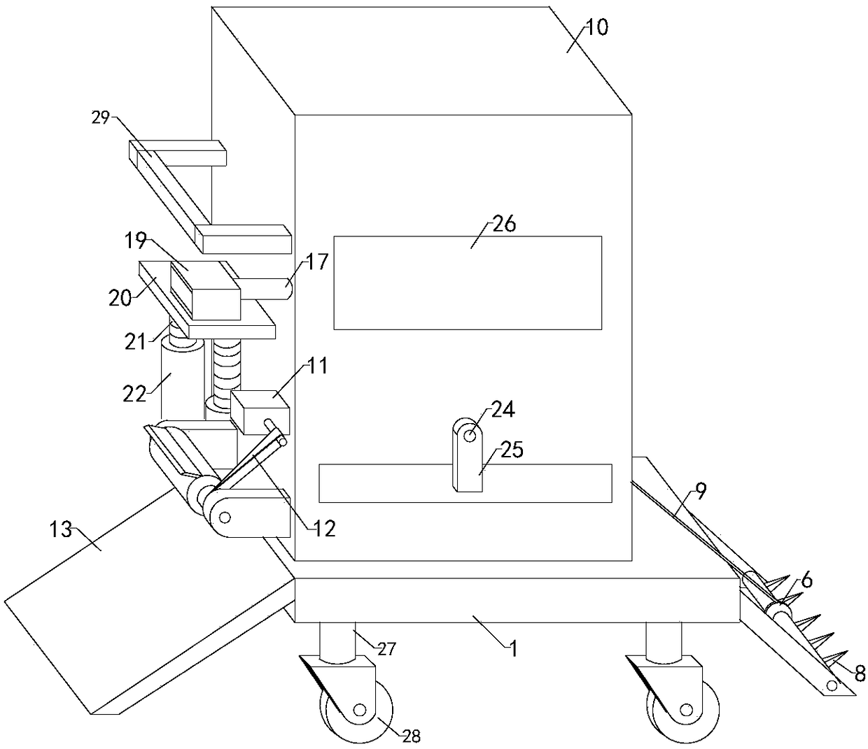
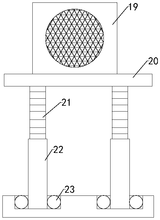
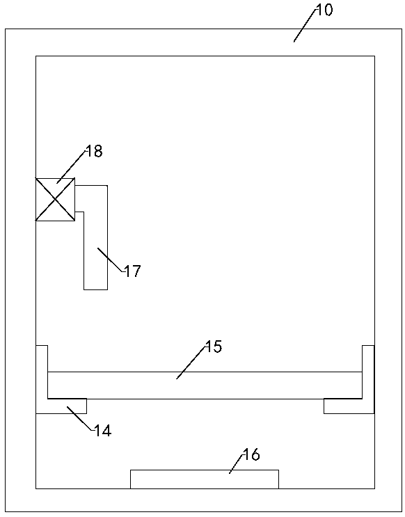
[0017] Such as Figure 1 to Figure 5 As shown, a pneumatic deicing and snow removal machine of the present invention includes a bottom plate 1, a fan 2, a compressor 3, a heating chamber 4, an electric heating rod, a driving gear 5, a driven gear 6, multiple sets of blades 7 and two sets of first Fixing frame and two sets of second fixing frame, two sets of first fixing frame and two sets of second fixing frame are respectively installed on the top and bottom of the bottom plate, and between the two sets of first fixing frame and two sets of second fixing frame A first rotating shaft and a second rotating shaft are respectively provided. The driving gear and the second gear are respectively sleeved on the first...


PUM


Abstract

The invention relates to the technical field of road environmental sanitary equipment, in particular to a pneumatic ice and snow removing machine. The pneumatic ice and snow removing machine comprisesa bottom plate, a fan, a compressor, a heating chamber, an electric heating rod, a drive gear, a driven gear, a plurality of shovel blades, two first fixing racks, two second fixing racks, a machinebody, two support racks, a rotary roller, a drive motor, a belt, a shovel plate, two slide rails, a filter screen plate, a communicating hose, a high-pressure water pump, a sprayer, a support device and a support plate and is characterized in that the compressor is located at the right output end of the fan; the machine body is mounted at the top end of the bottom plate, the machine body is provided with a working cavity inside, the left lateral wall of the machine body is provided with the open filter screen plate which is mounted between the two slide rails, and an electric heating plate isarranged in the working cavity; the left input end of the communicating hose is communicated with the sprayer. The pneumatic ice and snow removing machine is high in ice and snow processing degree, good in ice and snow removing effect, high in practicality, capable of effectively reasonably utilizing ice and snow and high in use reliability and cannot easily cause resource waste.

Description

technical field [0001] The invention relates to the technical field of road environmental sanitation equipment, in particular to a pneumatic snow removal machine. Background technique [0002] As everyone knows, a pneumatic snow removal machine is a device that compresses the air to generate kinetic energy to drive tools to remove snow on the road to ensure that pedestrians and vehicles can pass safely, and is widely used in daily life; existing The pneumatic snow removal machine includes a base plate, a fan, a compressor, a heating chamber, an electric heating rod, a driving gear, a passive gear, multiple sets of shovel blades, two sets of first fixing frames and two sets of second fixing frames, and two sets of first fixing frames and two sets of second fixing frames are respectively installed on the top and bottom ends of the bottom plate, and a first rotating shaft and a second rotating shaft are respectively arranged between the two groups of first fixing frames and the...

Claims


Application Information

Patent Timeline
IPC IPC(8): E01H5/09
CPCE01H5/09
Inventor 狄程楠
Owner 狄程楠
Why Eureka
Try Eureka