
A bolted connection joint between circular steel tube concrete column and steel beam outer ring plate

A technology for concrete columns and connecting nodes, which is applied in the direction of buildings and building structures, and can solve problems such as difficult to repair damage to pipelines, stress concentration, floor cracking, etc.

Active Publication Date: 2019-09-10
WUHAN UNIV OF SCI & TECH
View PDF7 Cites 0 Cited by
  • Summary
  • Abstract
  • Description
  • Claims
  • Application Information

AI Technical Summary

Problems solved by technology

[0005] The researchers conducted experimental research on the bolted connection joints between concrete filled steel tube columns and steel beams. The connectors used included outer ring plates, inner partitions, outwardly extending inner partitions, and T-shaped keys. The experimental research showed that the above bolted joints can make The plastic hinge of the node moves to the outside of the connector, but the stress concentration is serious at the bolt hole outside the flange of the steel beam on the tension side
Since the bolt holes in the flange of the steel beam are round holes, the frictional energy dissipation capacity between the steel beam and the connector cannot be fully utilized, and the cross-sectional area of ​​the flange of the steel beam is weakened at the round hole, resulting in serious stress concentration
[0006] For the joints where the upper flange of the steel beam and the connectors are only connected by bolts, it is not conducive to the actual use of the project
When subjected to a large load, due to the relative slippage between the upper flange of the steel beam and the connecting piece, the floor slab will crack, and the pipeline in the floor slab will also cause irreparable damage
In the bolted joints studied by previous researchers, the bolt holes in the lower flange of the steel beam are often round holes, which limits the relative slip energy consumption between the connector and the lower flange of the steel beam, and the energy consumption of the joint is actually still determined by the Plastic damage energy dissipation provides

Method used


Image

  • A bolted connection joint between circular steel tube concrete column and steel beam outer ring plate
  • A bolted connection joint between circular steel tube concrete column and steel beam outer ring plate
  • A bolted connection joint between circular steel tube concrete column and steel beam outer ring plate

Examples


Embodiment Construction

[0028] The present invention will be further described in detail below in conjunction with the accompanying drawings and embodiments.

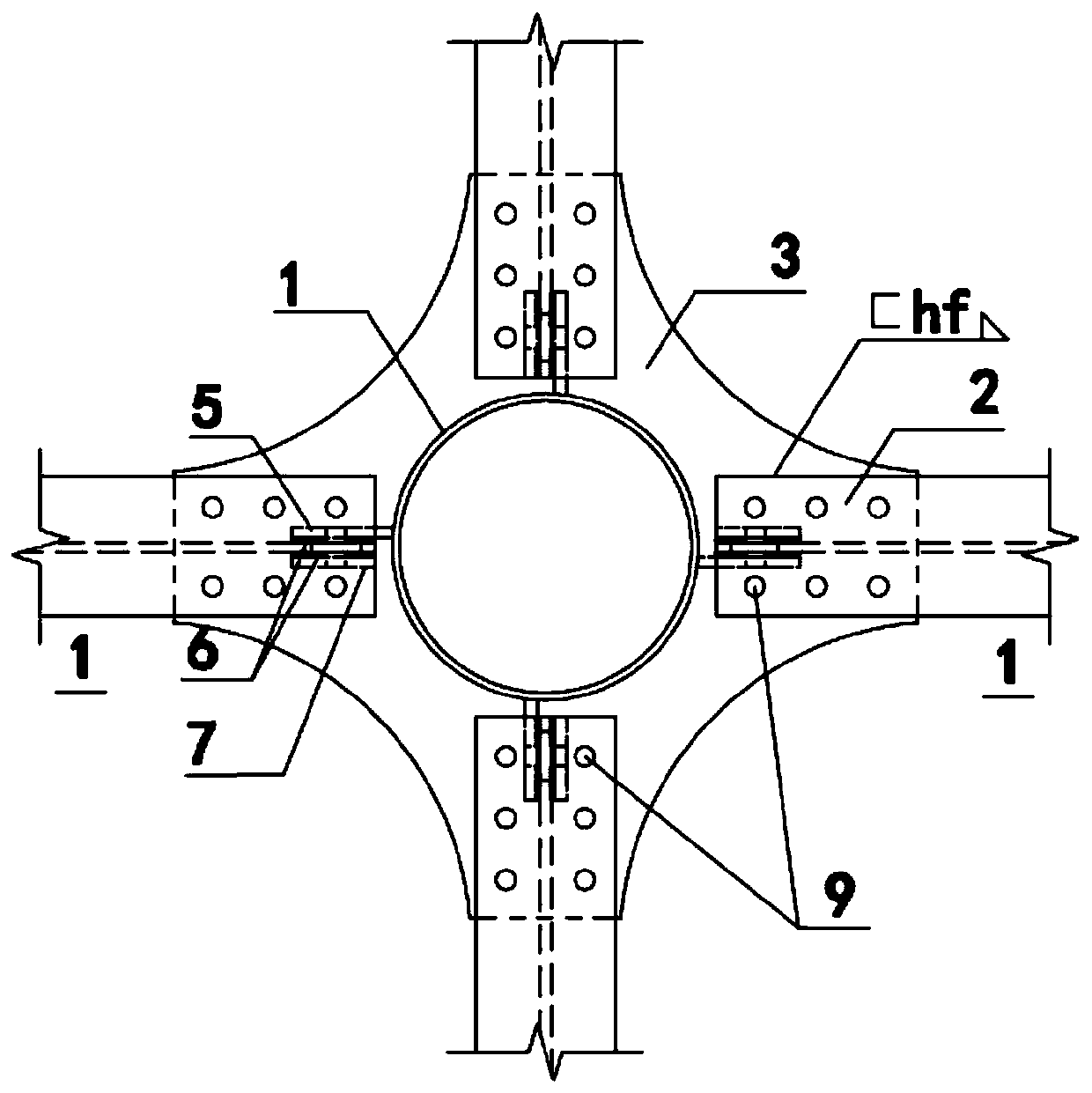
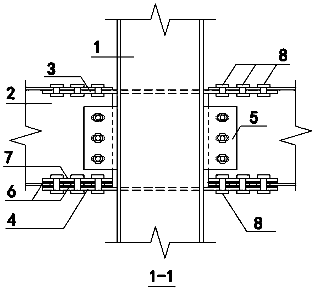
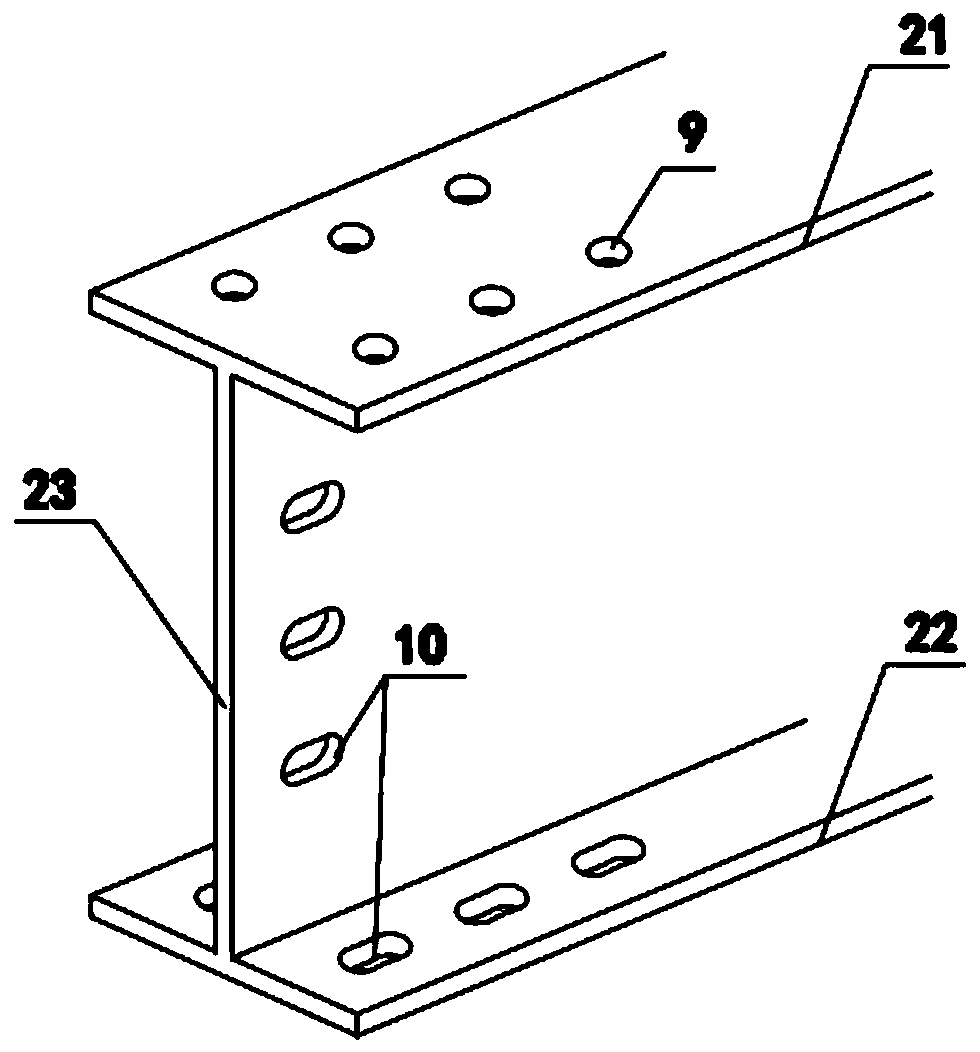
[0029] In Example 1, such as Figure 1-5As shown, the present invention is a circular steel pipe concrete column-steel girder outer ring plate bolt connection node, including a circular steel pipe concrete column 1, a steel beam 2 connected to the column, an upper outer ring plate 3, a lower outer ring plate 4 and The connecting plate 5, the steel beam 2 includes an upper flange 21, a lower flange 22 and a web 23, the upper outer ring plate 3 and the lower outer ring plate 4 are concave arc ring plates and the upper outer ring plate 3 is slotted 31, the steel beam web 23 is inserted into the groove 31, the steel beam upper flange 21 has a circular bolt hole 9, and the upper outer ring plate 3 has a circular bolt hole on the steel beam upper flange 21 A circular bolt hole 9 is also opened at the corresponding position, and the upper outer ring...


PUM


Abstract

The invention provides a circular steel pipe concrete column-steel beam outer annular plate bolted connection joint. The circular steel pipe concrete column-steel beam outer annular plate bolted connection joint comprises a circular steel pipe concrete column, steel beams, an upper side outer annular plate, a lower side outer annular plate, connecting plates, brass strips, cushion plates and high-strength bolts. The upper side outer annular plate, the lower side outer annular plate and the connecting plates are welded to the steel pipe column; grooves are formed in the upper side outer annularplate, web plates of the steel beams are inserted into the grooves, connecting strength is guaranteed through three-face weld all around, and the upper side outer annular plate and upper flanges areconnected through the high-strength bolts; and the web plates and lower flanges of the steel beams are both provided with long groove holes and connected with the connecting plates and the lower sideouter annular plate through the high-strength bolts correspondingly. According to the joint, the upper flanges of the steel beams and the upper side outer annular plate are in bolt welded connection,therefore, the situation that coherent plastic zones are formed at bolt holes in the inner sides of the annular plates and bolt holes in the outer sides of the flanges of the steel beams is avoided, and brittle fracture damage of weld seams is avoided; and bolt holes of the web plates of the steel beams and the bolt holes of the lower flanges of the steel beams are long groove holes, so that it isguaranteed that the outer annular plate bolted connection joint fully slides in the allowed rotating range, joint ductility is improved, and the friction energy consumption capability of the bolted connection positions of the lower flanges is given to better play.

Description

technical field [0001] The invention relates to the technical field of building structure engineering, in particular to a bolted connection node of a steel beam outer ring plate of a circular steel pipe concrete column. Background technique [0002] The concrete-filled steel pipe structure is formed by pouring concrete into thin-walled steel pipes. The steel pipe and concrete work together to make the steel pipe concrete structure have high bearing capacity, good ductility and energy consumption, superior plasticity and toughness, strong fire resistance, and convenient structural construction. [0003] Concrete-filled steel tube columns and steel beams constitute a frame structure system, which has a simple structure, rapid construction, and easy building layout. At present, the commonly used joint forms provided by my country's "Technical Specifications for Concrete Steel Tube Structures" (GB50936-2014) include externally reinforced ring joints and internally reinforced rin...

Claims


Application Information

Patent Timeline
Patent Type & Authority Patents(China)
IPC IPC(8): E04B1/24E04B1/58
Inventor 李伟李成玉郑镁杰商晨
Owner WUHAN UNIV OF SCI & TECH
Learn More