

Sealing oil cavity socket
A technology for sealing oil chambers and sockets, applied in engine components, machines/engines, gas turbine devices, etc., can solve the problems of increased maintenance times, prone to resonance, and large space occupied by the positioning seat, so as to overcome the inaccurate positioning and increase the The effect of oil storage and space saving
Pending Publication Date: 2018-06-12
于 强
View PDF4 Cites 0 Cited by
- Summary
- Abstract
- Description
- Claims
- Application Information
AI Technical Summary
Problems solved by technology
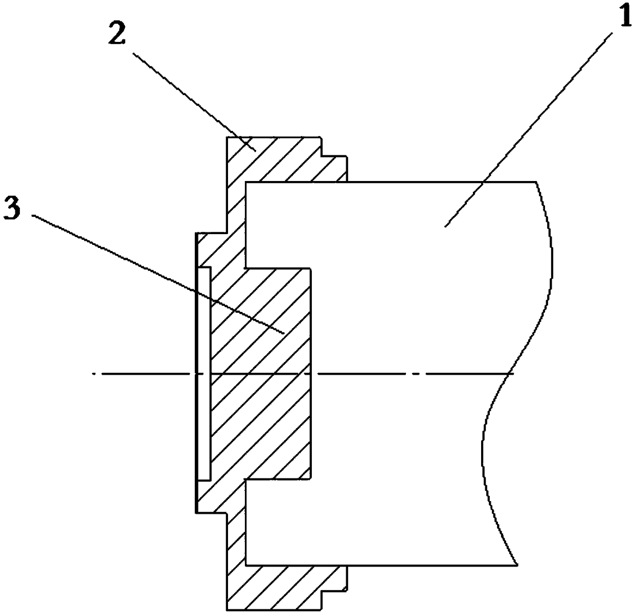
The existing structure of the sealing oil chamber sleeve is as follows: figure 2 As shown, the positioning seat is a cylindrical structure, which is bulky and poorly positioned, and is prone to resonance and high noise when the turbocharger is working; since the space of the engine is small, the positioning seat occupies The space is large, and the lubricating oil chamber of the turbocharger is relatively small, which increases the number of maintenance and increases the burden on the driver
Method used
View moreImage
Smart ImageViewing Examples

Examples
Embodiment Construction
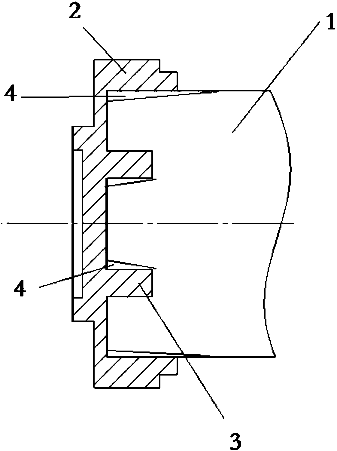
[0008] The present invention is specifically described below in conjunction with accompanying drawing, as figure 1 As shown, it includes an annular base 2, a positioning seat 3 is arranged in the middle of the base 2, and the positioning seat 3 is annular, and the inner side of the positioning seat 3 is provided with a tapered seat lining 4; the inner side of the annular base A tapered seat liner 4 is also provided; the bottom of the sealed oil chamber 1 is provided with a corresponding tapered surface.
[0009] The sealing seat lining material can be soft metal, such as copper; high temperature resistant rubber products can also be used.
Login to View More PUM
 Abstract
The invention discloses a sealing oil cavity socket which comprises an annular base, a positioning base is arranged at the middle of the base, the sealing oil cavity socket is characterized in that the positioning base is annular, a taper face seat lining is arranged on the inner side of the positioning base, a taper face seat lining is arranged on the inner side of the annular base, and a corresponding taper face is arranged at the bottom of a sealing oil cavity.
Description
technical field [0001] The invention relates to turbocharger technology, in particular to a sleeve. Background technique [0002] The working environment of the turbocharger is relatively harsh, and good lubrication is required to ensure normal operation. The existing structure of the sealing oil chamber sleeve is as follows: figure 2 As shown, the positioning seat is a cylindrical structure, which is bulky and poorly positioned, and is prone to resonance and high noise when the turbocharger is working; since the space of the engine is small, the positioning seat occupies The space is large, and the lubricating oil chamber of the turbocharger is relatively small, which increases the number of maintenance and increases the burden on the driver. Contents of the invention [0003] In order to solve the above-mentioned technical problems, the purpose of the present invention is to provide a well-positioned and small-sized sleeve. The specific technical solutions are as follo...
Claims
Login to View More Application Information
Patent Timeline
 Patent Type & AuthorityApplications(China)
IPC IPC(8): F02B39/14F02C6/12
CPCF02B39/14F02C6/12
Inventor于强
Owner于 强