

Ultra-wide-angle small imaging optical lens
An imaging optics, ultra-wide-angle technology, applied in optics, optical components, instruments, etc., can solve the problems of high price and small field of view, and achieve the effect of saving loading space, improving geometric transfer function, and reducing overall volume
Pending Publication Date: 2018-06-12
UNION OPTECH
View PDF0 Cites 0 Cited by
- Summary
- Abstract
- Description
- Claims
- Application Information
AI Technical Summary
Problems solved by technology
[0002] The existing micro-lens generally has a field of view around 80 degrees, and the actual field of view is small. There are also many fisheye lenses with a large field of view on the market. They are composed of many optical lenses and require precise molding and assembly. , so it is very expensive
Method used
View moreImage
Smart ImageViewing Examples

Examples
no. 1 example
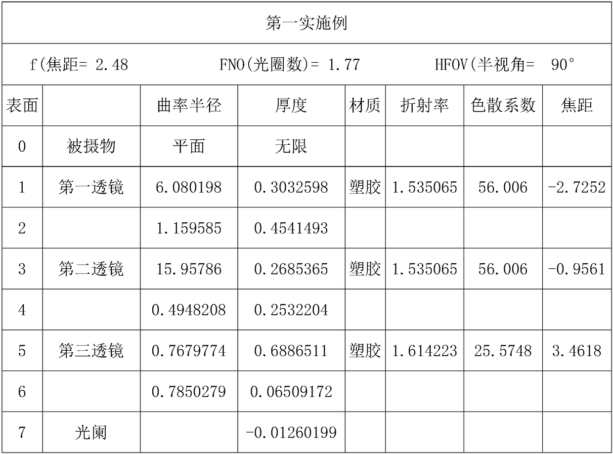
[0030] The data of the first embodiment are as follows:
[0031]
[0032]
[0033]
[0034]
[0035] The above is the detailed structural data of the embodiment. The maximum size of the image plane can reach 2.0 mm, and the unit of the data of the radius of curvature, thickness and focal length is mm. Surface 6, Surface 8 to Surface 13 are the aspheric coefficients, and A2-A16 are the 2-16 order aspheric coefficients of each surface.
Login to View More PUM
 Abstract
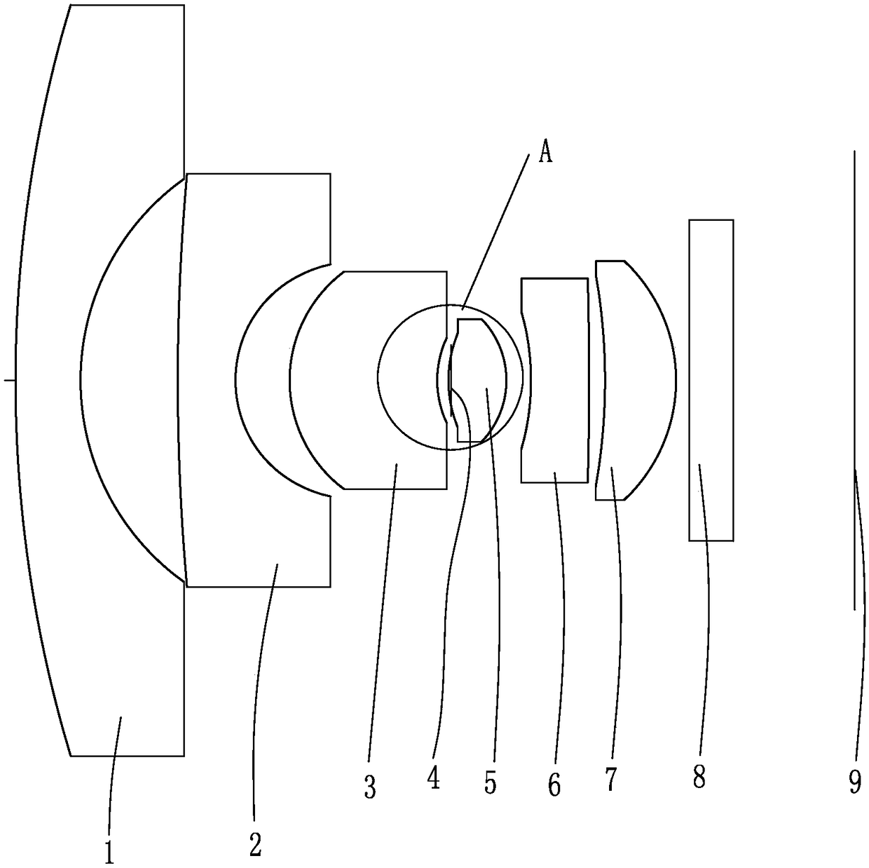
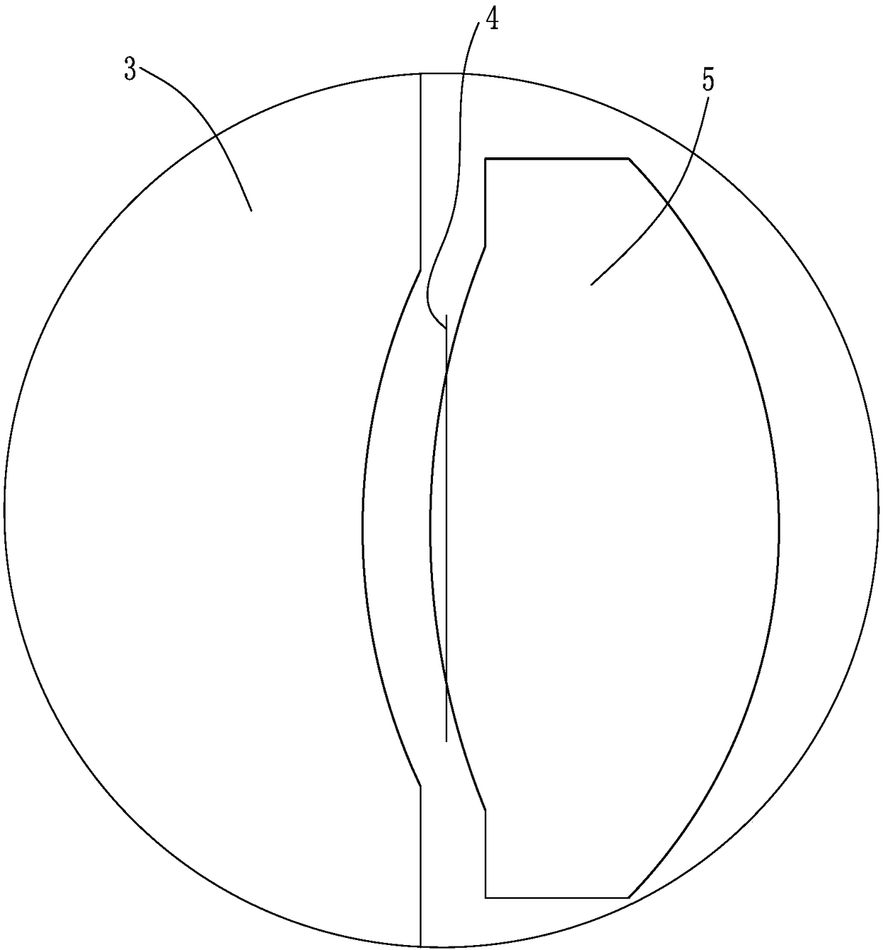
The invention relates to an ultra-wide-angle small imaging optical lens, which is sequentially provided with a first lens (1), a second lens (2), a third lens (3), a diaphragm aperture (4), a fourth lens (5), a fifth lens (6), a sixth lens (7), an optical filter (8) and a light sensing sheet (9) from an object surface to an image surface, wherein the aperture of the first lens (1) is D1, the distance between the first lens (1) and the light sensing sheet (9) is TL, the total focal length of the optical lens is f, and the aperture D1, the distance TL and the total focal length f meet the following conditions: f / TL is greater than 0.12 and less than 0.14, and D1 / TL is greater than 0.87 and less than 1.03. The ultra-wide-angle small imaging optical lens effectively rounds in wide-angle lightand realizes 180-degree ultra-wide-angle camera shooting.
Description
【Technical field】 [0001] The patent of the present invention relates to an ultra-wide-angle compact imaging optical lens. 【Background technique】 [0002] The existing micro-lens generally has a field of view around 80 degrees, and the actual field of view is small. There are also many fisheye lenses with a large field of view on the market. They are composed of many optical lenses and require precise molding and assembly. , so its price is very expensive. [0003] Due to the above-mentioned problems, it is necessary to propose a solution, and the present invention is made under such a background. 【Content of invention】 [0004] The technical problem to be solved by the present invention is to provide an ultra-wide-angle compact imaging optical lens for the above-mentioned deficiencies in the prior art. The ultra-wide-angle compact imaging optical lens can effectively gather large-angle light rays and realize 180° ultra-wide-angle imaging. [0005] To achieve the above ob...
Claims
Login to View More Application Information
Patent Timeline
 Patent Type & AuthorityApplications(China)
IPC IPC(8): G02B13/00G02B13/06G02B13/18
CPCG02B13/0045G02B13/06G02B13/18
Inventor鲍康倩肖明志
OwnerUNION OPTECH