
Adjustment and testing method and device for access logic of gate machine

A testing device and logic technology, applied in access control, rail transit ticket sales and checking equipment, turnstiles, automatic ticket checking equipment, access control fields, can solve the problems of occupying material and manpower, troublesome adjustment, waste of laboratory space, etc., to achieve efficiency improvement, Simplified process, the effect of saving test time

Pending Publication Date: 2018-06-12
北京中软万维网络技术有限公司
View PDF0 Cites 4 Cited by
  • Summary
  • Abstract
  • Description
  • Claims
  • Application Information

AI Technical Summary

Problems solved by technology

However, the test center basically installs the same gate equipment as the site, so the adjustment process must first open the gate door, then close the door after adjustment, and then adjust and verify the sensor alignment. Some manufacturers' sensors are Installed on the door panel, although the alignment can be kept accurate, but the adjustment is more troublesome
[0008] Furthermore, the layout of sensors is closely related to the traffic logic. Each manufacturer is different in the number, layout, and sensitivity of sensors. For a city, there may be many rail transit lines, and there will be A variety of traffic logics, to adapt to the physical characteristics of the local population, requires a variety of traffic logics to adapt to it. After the owner establishes the test center, if each type of gate needs to be equipped with a corresponding prototype test environment in the laboratory, it will be very busy. Material and manpower and waste of laboratory space

Method used


Image

  • Adjustment and testing method and device for access logic of gate machine
  • Adjustment and testing method and device for access logic of gate machine
  • Adjustment and testing method and device for access logic of gate machine

Examples


Embodiment Construction

[0055] Below in conjunction with accompanying drawing, the present invention is described in further detail:

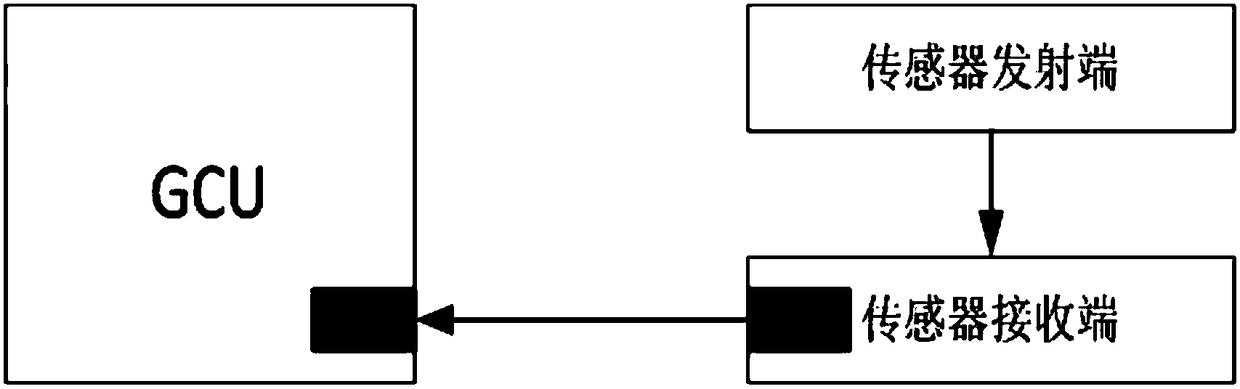
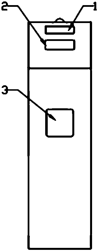
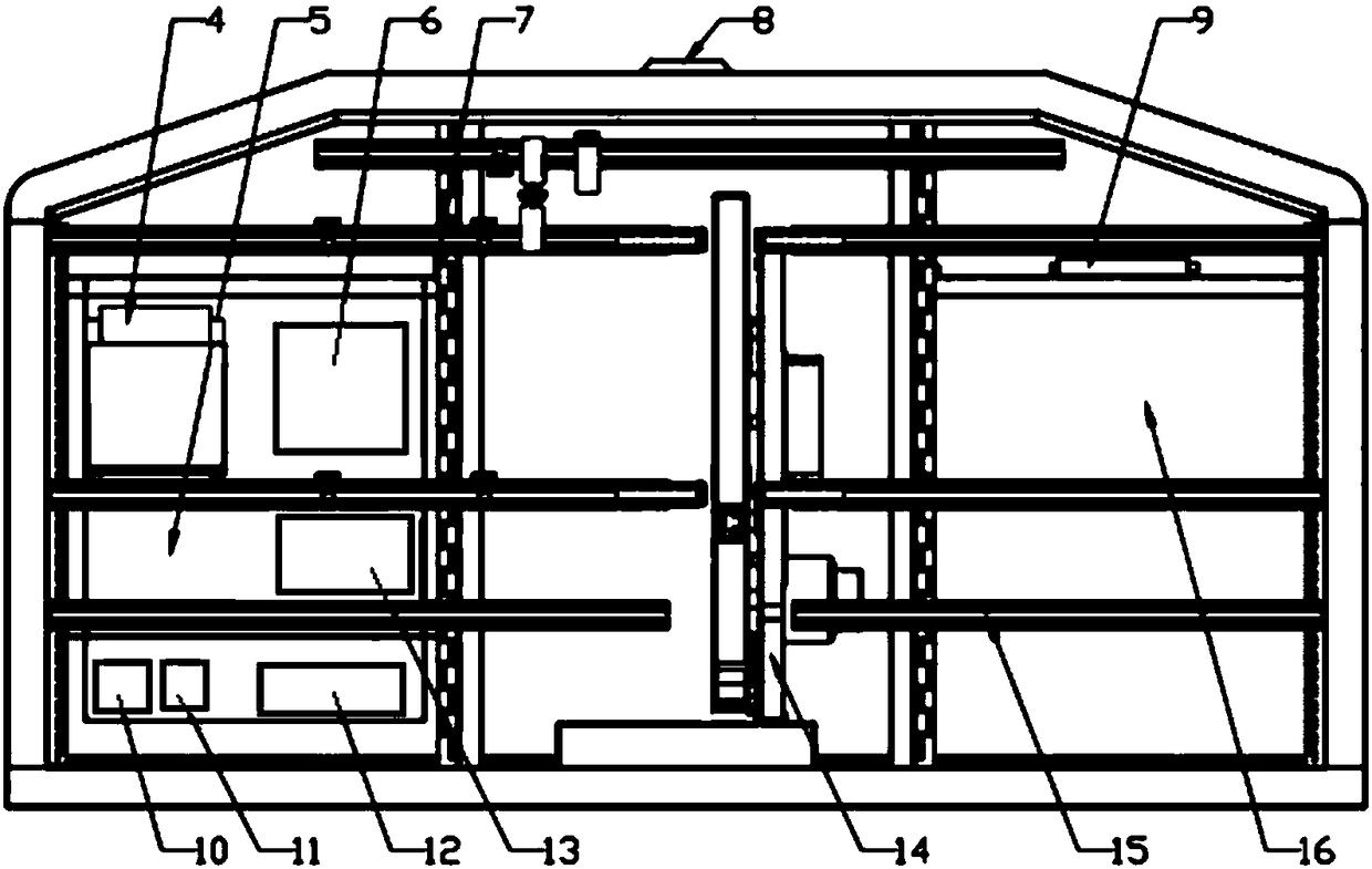
[0056] Such as figure 2 and image 3 As shown, the adjusting and testing device for gate passage logic of the present invention includes a test frame made of sheet metal technology, a passenger display screen 1, a card swiping area antenna 2, a passage indicator 3, an industrial computer 4, a passage logic debugging and detection module 5, Buzzer 7, warning light 8, card reader 9, leakage protection switch 10, filter 11, DC power supply 12, slide bar 15, traffic behavior recording playback module 16, sensor is installed on slide bar 15, and sensor includes 16 - 24 pairs of through-beam sensors.

[0057] Doors of different manufacturers use different traffic logics. The doors and traffic logic are bound. Different traffic logics lead to different positions of the cross-beam sensors. In actual use, which manufacturer’s door is detected depends on this The invented t...


PUM


Abstract

The invention provides an adjustment and testing method and device for the access logic of a gate machine, and belongs to the fields of rail traffic ticket selling and checking equipment, access control, gate machines, and automatic ticket checking equipment. The device comprises a testing frame pedestal, two testing platform supports, and an access logic debugging and detection module. The bottoms of the two testing platform supports are installed on the testing frame pedestal, and are parallel to each other, wherein a gate machine channel is formed between the two testing platform supports.Each testing platform support is provided with a longitudinal support and a plurality of sliding rods. The upper and lower ends of the longitudinal supports are respectively fixed on the correspondingtesting platform supports. Two ends of each sliding rod are respectively fixed on the corresponding longitudinal support, and can be fixedly installed at different heights on the corresponding longitudinal support. Each sliding rod is connected with a plurality of adjustable supports, and the adjustable supports can move and be fixed on the sliding rods. Each adjustable support is provided with athru-beam sensor.

Description

technical field [0001] The invention belongs to the field of rail transit ticket sales and inspection equipment, access control, access control, gates, and automatic ticket inspection equipment, and in particular relates to a device and method for adjusting and testing the passage logic of a gate. Background technique [0002] At present, the gates used in the fields of rail transit fare collection equipment, access control, access control, gates, automatic ticket inspection equipment, etc. all have gate passage logic control devices that determine the behavior of passers-by, such as figure 1 As shown, it includes the combination of the transmitting end and receiving end of the opposite-beam infrared photoelectric sensor installed in the two gates and the gate unit control unit (GCU). The transmitting end emits infrared light in the invisible band and is received by the receiving end. Referred to as the sensor optical path, after pedestrians enter the passage, their bodies, ...

Claims


Application Information

Patent Timeline
IPC IPC(8): G05B23/02
CPCG05B23/0213G05B2219/24065
Inventor 杜潜李棋瑞郭建树陈国林陈跃飞齐春阳程明亮柳振强高鹏飞王建坤蔡晓曼王子印贾利明
Owner 北京中软万维网络技术有限公司
Features
  • Generate Ideas
  • Intellectual Property
  • Life Sciences
  • Materials
  • Tech Scout
  • Unparalleled Data Quality
  • Higher Quality Content
  • 60% Fewer Hallucinations
Learn More