Novel measurement experiment instrument for internal magnetic field distribution of multifunctional solenoid

A magnetic field distribution and solenoid technology, applied in the field of experimental instruments, can solve the problems of no fixed device for the solenoid, unreasonable partial structure design, and difficulty in moving the Hall sensor, etc., and achieves structural layout specifications, novel design ideas, and method feasible effect

Pending Publication Date: 2018-06-12
ZHEJIANG UNIV CITY COLLEGE
View PDF10 Cites 4 Cited by
  • Summary
  • Abstract
  • Description
  • Claims
  • Application Information

AI Technical Summary

Problems solved by technology

[0002] Solenoid magnetic field distribution measurement is an important experimental project in the Department of Physics and Electricity of the university. The solenoid magnetic field distribution is not only related to the number of coil turns, but also related to the magnitude of the current passing through the coil wire. At present, the experiment of measuring the solenoid magnetic field distribution Although there are some experimental instruments and devices in the market and physical laboratories, these experimental instruments all have some defects: (1) the solenoid used in the experiment has no fixing device; (2) it is difficult for the experimenter to place the Hall sensor accurately on the coil. The central position and the movement in the direction of the axis; (3) It is impossible to measure the magnetic field distribution experiment on the axis of the solenoid and to verify the magnetic field superposition (or change with the number of turns) experiment on the same experimental instrument; (4) The local structure design of the existing experimental device is very unreasonable

Method used


Image

  • Novel measurement experiment instrument for internal magnetic field distribution of multifunctional solenoid
  • Novel measurement experiment instrument for internal magnetic field distribution of multifunctional solenoid
  • Novel measurement experiment instrument for internal magnetic field distribution of multifunctional solenoid

Examples


Embodiment Construction

[0030] The present invention will be further described below in conjunction with the examples. The description of the following examples is provided only to aid the understanding of the present invention. It should be pointed out that for those skilled in the art, without departing from the principles of the present invention, some improvements and modifications can be made to the present invention, and these improvements and modifications also fall within the protection scope of the claims of the present invention.

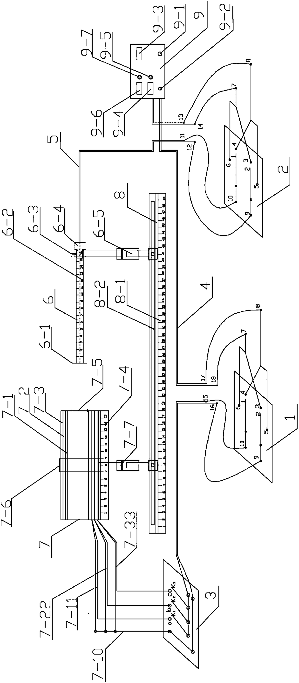
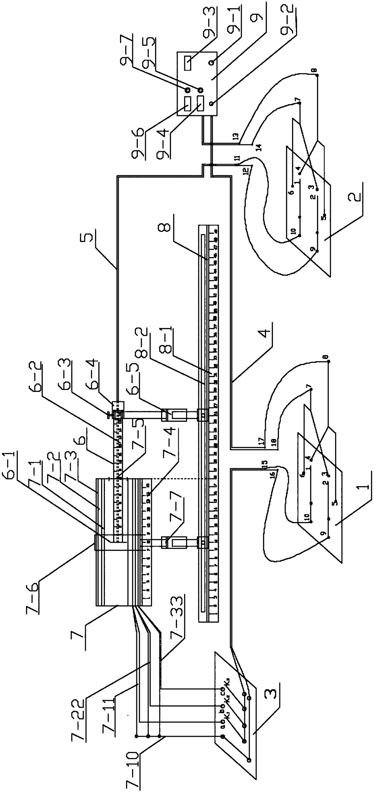
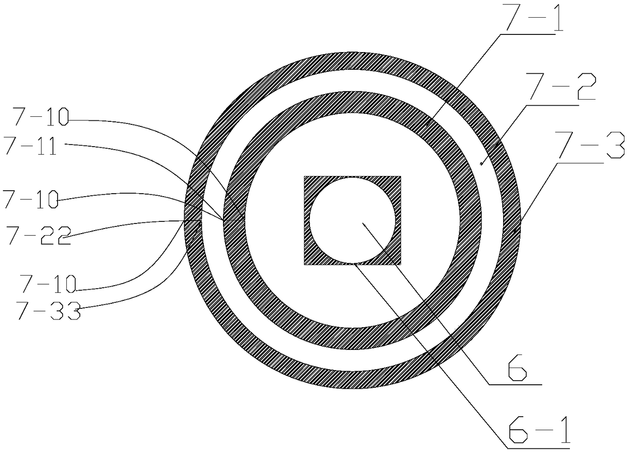
[0031] The new multifunctional solenoid internal magnetic field distribution measurement experimental instrument includes: three-coil solenoid forward and reverse wiring board 1, Hall plate current supply line forward and reverse wiring board 2, three-coil solenoid connection switch wiring board 3. Three-coil solenoid current supply line 4. Hall plate current supply line 5. Hall plate fixed copper tube 6. Three-coil solenoid 7. Solenoid and Hall plate fixed coppe...


PUM


Abstract

The invention relates to a novel measurement experiment instrument for internal magnetic field distribution of a multifunctional solenoid. The measurement experiment instrument comprises a three-coilsolenoid forward-and-reverse connection board, a Hall plate current power supply line forward-and-reverse connection board, a three-coil solenoid connection switch connection board, a three-coil solenoid current power supply line, a Hall plate current power supply line, a Hall plate fixing copper tube, a three-coil solenoid, a solenoid and Hall plate fixing copper tube support base slide, and an electric cabinet. Three coils of the three-coil solenoid include an inner coil, a middle coil and an outer coil. Each coil guides out two guide lines. The inner coil guides out a three-coil public lineand an inner coil guide line, the middle coil guides out the three-coil public line and an middle coil guide line, and the outer coil guides out the three-coil public line and an outer coil guide line. The measurement experiment instrument has the advantages of novelty in overall structure design thinking, solution feasibility, and standard and reasonable structural layout.

Description

technical field [0001] The invention relates to an experiment instrument, in particular to a novel multifunctional solenoid internal magnetic field distribution measurement experiment instrument. Background technique [0002] Solenoid magnetic field distribution measurement is an important experimental project in the Department of Physics and Electricity of the University. The solenoid magnetic field distribution is not only related to the number of coil turns, but also related to the magnitude of the current passing through the coil wire. At present, the experiment of measuring the solenoid magnetic field distribution Although there are some experimental instruments and devices in the market and physical laboratories, these experimental instruments all have some defects: (1) the solenoid used in the experiment has no fixing device; (2) it is difficult for the experimenter to accurately place the Hall sensor on the coil. The central position and the movement in the direction...

Claims


Application Information

Patent Timeline
Patent Type & Authority Applications(China)
IPC IPC(8): G09B23/18G01R33/10G01R33/02
CPCG09B23/181G01R33/02G01R33/10
Inventor 张锐波范哲焱陶晓锋
Owner ZHEJIANG UNIV CITY COLLEGE
Why Eureka
Try Eureka