Arc extinguishing spray pipe for gas generating and arc extinguishing device

An arc extinguishing device and arc extinguishing technology, used in electrical components, high-voltage air circuit breakers, electrical switches, etc., can solve problems such as poor circuit contact, strong impact force, skin arc burns, etc., to improve equipment safety and reduce airflow. Impact force, the effect of improving the safety factor

Inactive Publication Date: 2018-06-12
毛根善
View PDF0 Cites 2 Cited by
  • Summary
  • Abstract
  • Description
  • Claims
  • Application Information

AI Technical Summary

Problems solved by technology

[0002] As we all know, due to the large current in the high-voltage circuit, a high-energy arc will be generated while breaking, which will have a great impact on electrical equipment. The conventional method is to install an arc extinguishing device on the isolating switch device or circuit breaker. The arc extinguishing device is set up to prevent unnecessary losses caused by the arc sparks generated when the contacts are disconnected, because the arc sparks will be generated when the contacts or switches are turned on and off, which may cause the following hazards: 1. Burning contacts First-class, as time goes by, the circuit will be poorly contacted, causing damage to the circuit
2. It may cause arc burns to human eyes, skin, etc., and cause unpredictable harm to the human body
3. In some places sensitive to arc sparks, such as gas plants or places filled with flammable gases, even a little arc spark may cause an explosion, etc.
4. Arc sparks may cause breakdown damage to some electronic products (such as integrated circuits) along with the circuit.
[0003] At present, the most commonly used arc extinguishing device is a gas-generating arc-extinguishing device. The gas-generating arc-extinguishing device includes an arc-extinguishing chamber and a driving mechanism. At this time, the current forms a loop through the drainage rod, the transmission mechanism, the moving and static contacts of the arc extinguishing chamber, and the high-voltage terminal on the side of the knife seat, so as to avoid the high-energy arc from the knife of the high-voltage switch. During the driving process, the extinguishing The dynamic and static contacts in the arc chamber are separated to form an arc, and the arc burns the gas-producing plastic in the arc extinguishing chamber to form a high-pressure airflow to blow off the arc to achieve the purpose of arc extinguishing. Due to the current jet port of the arc extinguishing chamber and the supporting safety device, As a result, the high-energy arc has a longer distance to be pulled up through the gas nozzle, and the arc extinguishing effect is poor, and because there are many supporting facilities around it, it is more harmful. The impact force is stronger when the nozzle is ejected, and the risk factor is greater

Method used


Image

  • Arc extinguishing spray pipe for gas generating and arc extinguishing device
  • Arc extinguishing spray pipe for gas generating and arc extinguishing device

Examples


Embodiment Construction

[0021] In order to make the technical means, creative features, objectives and beneficial effects realized by the present invention easy to understand, the present invention will be further described below in conjunction with specific embodiments.

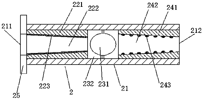
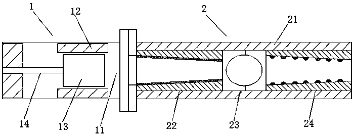
[0022] As shown in the figure, an arc extinguishing nozzle for a gas generation arc extinguishing device, the arc extinguishing nozzle 2 is arranged at the port of the gas injection hole 11 of the arc extinguishing chamber 1 in the arc extinguishing device, and the arc extinguishing nozzle 2 It includes an insulating sleeve 21 and an air inlet 211 and an air outlet 212 arranged on both sides of the insulating sleeve. The inner cavity of the pipe 21 is provided with a diversion chamber 22, a choke chamber 23 and a buffer chamber 24 sequentially along the air inlet 211 to the air outlet 212;

[0023] Specifically analyze the structure of the diversion chamber 22: the diversion chamber 22 includes a heat-insulation inner sleeve I221 m...


PUM


Abstract

The invention relates to an arc extinguishing spray pipe for a gas generating and arc extinguishing device. The arc extinguishing spray pipe comprises an insulating sleeve, wherein the insulating sleeve is internally provided with a flow guiding chamber, a flow resisting chamber and a buffer chamber in sequence, the three chambers complement each other, simultaneously act on arc extinguishing andreduce the air impact to the lowest, the flow guiding chamber is internally provided with a conical thermal insulation inner sleeve I and is provided with a gas generating and arc extinguishing plastic layer at the same time, the gap gradually becomes smaller when an air flow passes through the conical cavity, the arc energy is concentrated, the plastic layer is gasified, the air flow after the gasification is concentrated around the arc again, and the arc is gradually elongated while the arc energy is consumed. When the arc with the energy being reduced passes through the flow resisting chamber, the flow resisting chamber is provided with a blocking ball at the central position, so that the air flow and the arc simultaneously collide the blocking ball made of an insulating material and then flow around, and the arc can be effectively extinguished in the step. Meanwhile, the impact force of the air flow is reduced, then the air flow flows through the buffer chamber, so that the impactforce of the air flow is further reduced, and the safety coefficient of the device is improved.

Description

technical field [0001] The invention relates to an arc-extinguishing device in a high-voltage line, in particular to an arc-extinguishing nozzle for a gas-generating arc-extinguishing device. Background technique [0002] As we all know, due to the large current in the high-voltage circuit, a high-energy arc will be generated while breaking, which will have a great impact on electrical equipment. The conventional method is to install an arc extinguishing device on the isolating switch device or circuit breaker. The arc extinguishing device is set up to prevent unnecessary losses caused by the arc sparks generated when the contacts are disconnected, because the arc sparks will be generated when the contacts or switches are turned on and off, which may cause the following hazards: 1. Burning contacts First-class, as time goes by, the circuit will be poorly connected, causing damage to the circuit. 2. It may cause arc burns to human eyes and skin, and cause unpredictable harm ...

Claims


Application Information

Patent Timeline
Patent Type & Authority Applications(China)
IPC IPC(8): H01H33/22H01H33/72
CPCH01H33/22H01H33/72
Inventor 毛根善
Owner 毛根善
Why Eureka
Try Eureka