Steel wire shelling device

A steel wire and peeling technology, which is applied in the direction of metal extrusion cleaning equipment, metal processing equipment, manufacturing tools, etc., can solve the problem that there is no peeling treatment device, etc., and achieve convenient and fast processing, convenient and fast adjustment, and simple structure reasonable effect

Pending Publication Date: 2018-06-15
WUXI CHANGXIN TECH
View PDF7 Cites 0 Cited by
  • Summary
  • Abstract
  • Description
  • Claims
  • Application Information

AI Technical Summary

Problems solved by technology

At present, there is no ideal shelling treatment device before steel wire drawing

Method used


Image

  • Steel wire shelling device
  • Steel wire shelling device
  • Steel wire shelling device

Examples


Embodiment Construction

[0012] The specific embodiments of the present invention will be further described below in conjunction with the accompanying drawings.

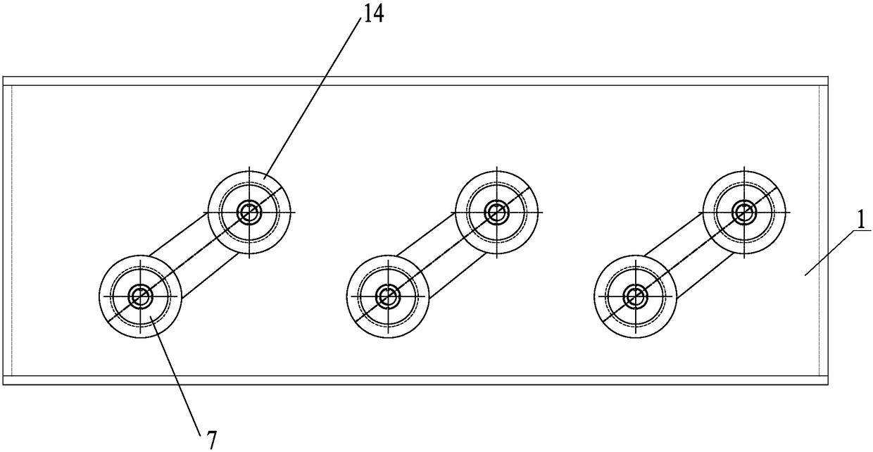
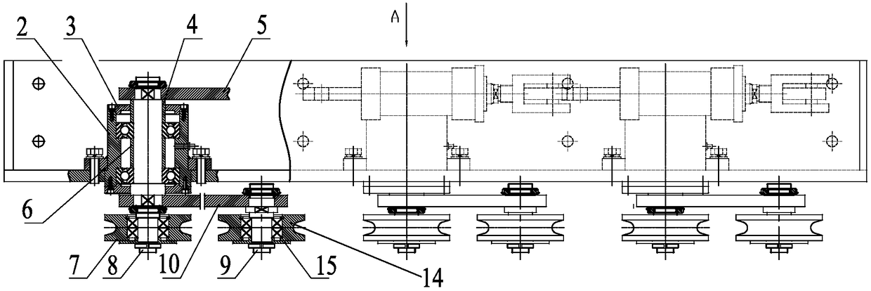
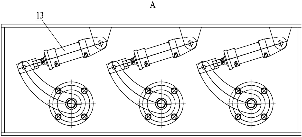
[0013] Figure 1~3 Among them, including support frame 1, bearing seat 2, end cover 3, first bushing 4, first connecting plate 5, second bushing 6, shelling wheel 7, rotating shaft 8, fixed shaft 9, second connecting plate 10 , Fixed plate 11, connecting block 12, hydraulic cylinder 13, second shelling wheel 14, pressing plate 15 etc.

[0014] Such as Figure 1~3 As shown, the present invention is a kind of steel wire peeling device, comprises support frame 1, and described support frame 1 is provided with several groups of shelling structures, and each group of described shelling structures all includes the rotating shaft that is arranged on the support frame 1 8. The rotating shaft 8 is placed on the shaft diameter of the end in the support frame 1 to rotate and is provided with a first connecting plate 5, and the shaft diameter of the r...


PUM

PropertyMeasurementUnit
diameteraaaaaaaaaa

Abstract

The invention belongs to the technical field of steel wire drawing equipment, and relates to a steel wire shelling device. The steel wire shelling device comprises a supporting frame. A plurality of sets of shelling structures are arranged on the supporting frame. Each set of the shelling structure comprises a rotating shaft which is arranged on the supporting frame in a rotating mode. The shaft diameter portion of the end, located inside the supporting frame, of each rotating shaft is provided with a first connecting plate in a rotating mode. The shaft diameter portion, stretching out of theouter end of the supporting frame, of each rotating shaft is provided with a second connecting plate and a first shelling wheel. The second connecting plates can rotate on the corresponding rotating shafts, and the first shelling wheels and the rotating shafts can rotate synchronously. The second connecting plates are provided with fixing shafts, and the fixing shafts are provided with second shelling wheels in a rotating mode. The shelling structures further comprise hydraulic cylinders, and the connecting ends of the hydraulic cylinders are connected with the supporting frame in a rotating mode. Piston rods of the hydraulic cylinders drive the second connecting plates to rotate. The steel wire shelling device is simple and reasonable in structure, and oxide skin and rust on the surface of a steel wire to be drawn can be effectively shelled.

Description

technical field [0001] The invention belongs to the technical field of steel wire drawing equipment, and relates to a steel wire peeling device. Background technique [0002] In production operations, it is a common processing method to draw steel wires with larger diameters to meet the required specifications according to the actual needs of customers. Since the steel wire to be drawn will form scale and rust on the surface after being placed for a long time, it is necessary to remove the scale and rust on the surface of the steel wire before drawing the steel wire. At present, there is no ideal shelling treatment device before steel wire drawing. Contents of the invention [0003] In view of the above problems, the present invention provides a steel wire peeling device, which has a simple and reasonable structure and can effectively peel off the scale and rust on the surface of the steel wire to be drawn. [0004] According to the technical solution of the present inve...

Claims


Application Information

Patent Timeline
Patent Type & Authority Applications(China)
IPC IPC(8): B21C43/04
CPCB21C43/04
Inventor 袁明
Owner WUXI CHANGXIN TECH
Why Eureka
Try Eureka