
Laser marking device and method and storage medium

A laser marking method and laser marking technology are applied in the field of laser marking devices, which can solve the problems of increased equipment cost and control cost, inability to mark, and inability to mark the inner surface, and achieve simple structure, cost saving, and expansion. The effect of the marking range

Inactive Publication Date: 2018-06-15
MAXPHOTONICS CORP
View PDF9 Cites 2 Cited by
  • Summary
  • Abstract
  • Description
  • Claims
  • Application Information

AI Technical Summary

Problems solved by technology

[0002] At present, for the marking of ring-shaped items such as rings, laser marking machines are usually used to mark with a rotary table. The marking of ring-shaped items is divided into outer surface marking and inner surface marking, and rotary marking Generally, the device can only mark the outer surface of the ring-shaped object, but cannot mark the inner surface; while there is a type of rotating table with adjustable angle that can realize the marking on the inner surface, but the equipment cost and control cost increase , and when performing rotary marking, because the marking object is raised, the laser focus may exceed the adjustment range of the laser marking machine, resulting in marking failure; in addition, the marking range of the existing laser marking machine is limited to Parallel to the plane where the laser focus is located under the field mirror, the specific marking range in this plane is determined by the specifications of the field mirror, which limits the application range of the laser marking machine

Method used


Image

  • Laser marking device and method and storage medium
  • Laser marking device and method and storage medium
  • Laser marking device and method and storage medium

Examples


Embodiment Construction

[0031] In order to enable those skilled in the art to better understand the solutions of the present invention, the technical solutions in the embodiments of the present invention will be clearly and completely described below in conjunction with the drawings in the embodiments of the present invention. Unless otherwise defined, all technical and scientific terms used herein have the same meaning as commonly understood by one of ordinary skill in the technical field of the invention. The terms used herein in the description of the present invention are for the purpose of describing specific embodiments only, and are not intended to limit the present invention. The terms "comprising" and "having" and any variations thereof in the description and claims of the present invention and the above drawings are intended to cover a non-exclusive inclusion. For example, a process, method, system, product or device comprising a series of steps or units is not limited to the listed steps o...


PUM


Abstract

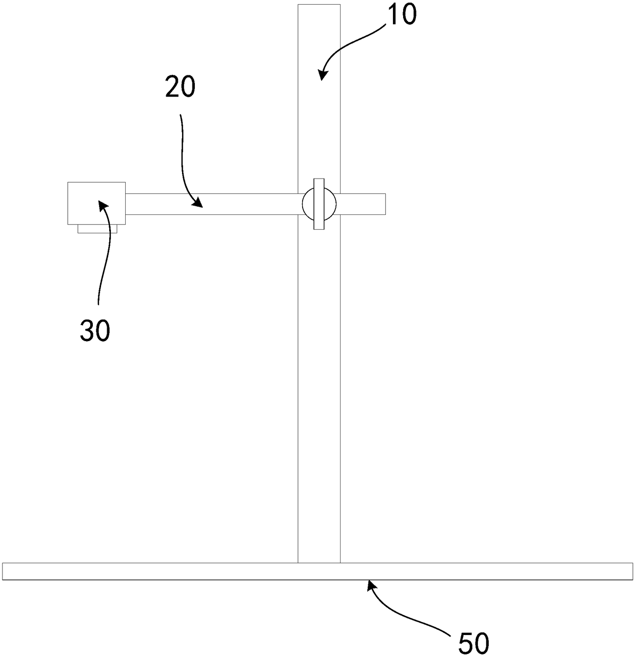
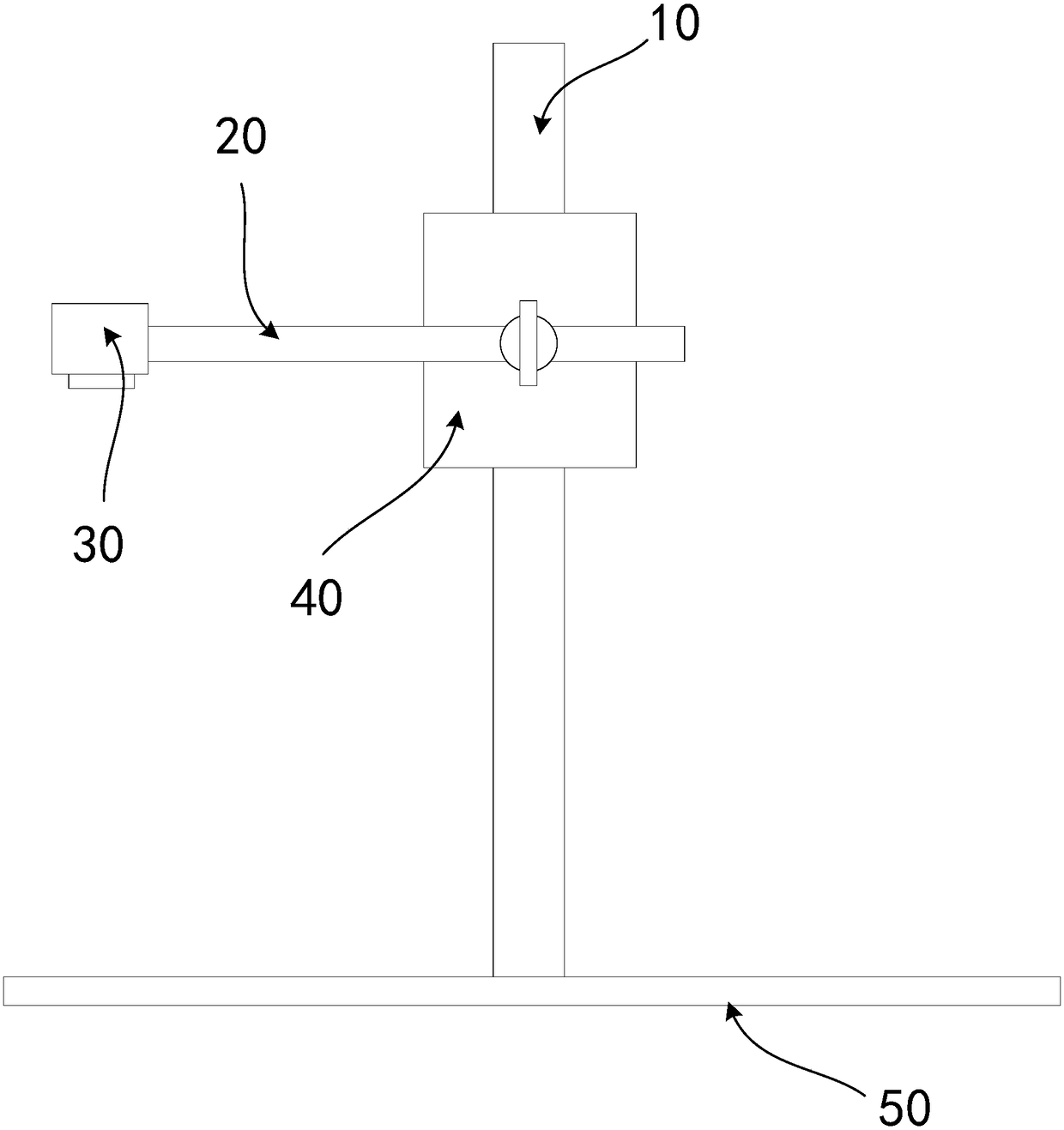
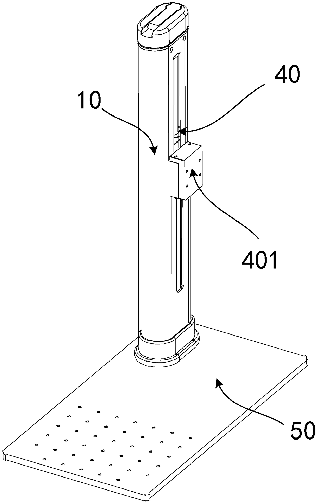
The embodiment of the invention belongs to the technical field of laser marking, and relates to a laser marking device. The laser marking device comprises a laser marking machine and a mounting frame,wherein the mounting frame comprises a mounting column and a rotating arm, a laser head of the laser marking machine is located at one end of the rotating arm, and the rotating arm can drives the laser head to conduct rotating movement along a vertical face based on the mounting column. According to the scheme provided by the embodiment of the invention, by changing the cross arm part of a mounting frame of a laser head in the prior art from an original fixed invariant part to the rotatable rotating arm, the incidence angle of a laser is changed accordingly, under the condition that the costis saved, the outer surface of a to-be-marked product can be marked, the inner surface of the to-be-marked product can also be marked, and the marking range is expanded. The invention further providesa laser marking method and a storage medium for the laser marking device.

Description

technical field [0001] The embodiments of the present invention belong to the technical field of laser marking, and in particular relate to a laser marking device, method and storage medium. Background technique [0002] At present, for the marking of ring-shaped items such as rings, laser marking machines are usually used to mark with a rotary table. The marking of ring-shaped items is divided into outer surface marking and inner surface marking, and rotary marking Generally, the device can only mark the outer surface of the ring-shaped object, but cannot mark the inner surface; while there is a type of rotating table with adjustable angle that can realize the marking on the inner surface, but the equipment cost and control cost increase , and when performing rotary marking, because the marking object is raised, the laser focus may exceed the adjustment range of the laser marking machine, resulting in marking failure; in addition, the marking range of the existing laser mar...

Claims


Application Information

Patent Timeline
Patent Type & Authority Applications(China)
IPC IPC(8): B23K26/362B23K26/08B23K26/70
CPCB23K26/08B23K26/361B23K26/702
Inventor 武晓花蒋峰
Owner MAXPHOTONICS CORP
Learn More