
Steel plate surface shot-blasting method

A steel plate and shot blasting machine technology, applied in the direction of abrasives, metal processing equipment, manufacturing tools, etc., can solve the problems of low production efficiency, hidden safety hazards, inability to produce steel plates, and a large amount of residual shot, so as to meet the needs of production rhythm and prevent Nodulation of Hearth Rolls and Improvement of Production Efficiency

Active Publication Date: 2018-06-15
SHANDONG IRON & STEEL CO LTD
View PDF6 Cites 2 Cited by
  • Summary
  • Abstract
  • Description
  • Claims
  • Application Information

AI Technical Summary

Problems solved by technology

However, the shot blasting machine equipment produced by the above-mentioned companies has high requirements on the shape of the steel plate, which brings the following two main problems: (1) The shot blasting machine requires that the unevenness of the steel plate is less than 10mm / m, if the unevenness of the steel plate is greater than 10mm / m , the shot blasting opportunity will alarm, and the steel plate cannot be thrown for production; (2) For the steel plate with an unevenness less than 10mm / m, a large amount of shot will remain on the upper surface of the steel plate after shot blasting, and it is necessary to manually remove the shot on the roller table, which is extremely labor intensive Large, low production efficiency and potential safety hazards

Method used


Image

  • Steel plate surface shot-blasting method

Examples


Embodiment Construction

[0027] The present invention will be described in detail below in conjunction with examples. Each example is provided by way of explanation of the invention, not limitation of the invention. In fact, those skilled in the art will recognize that modifications and variations can be made in the present invention without departing from the scope or spirit of the invention. For example, features illustrated or described as part of one embodiment can be used on another embodiment to yield a still further embodiment. Therefore, it is intended that the present invention includes such modifications and variations as come within the scope of the appended claims and their equivalents.

[0028] According to an embodiment of the present invention, a method of shot blasting on the surface of a steel plate is provided, using a shot blasting machine to blast the surface of the steel plate, comprising the following steps:

[0029] (1) Hoist the steel plate with a thickness of 6-120mm to the ...


PUM

PropertyMeasurementUnit
diameteraaaaaaaaaa
diameteraaaaaaaaaa
thicknessaaaaaaaaaa

Abstract

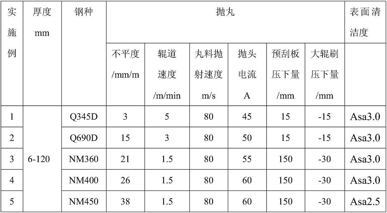
The invention provides a steel plate surface shot-blasting method. The steel plate surface shot-blasting method utilizes a shot-blasting machine for shot-blasting a surface of a steel plate, and comprises the following steps of (1) lifting the steel plate with the thickness being 6 to 120mm to an inlet roller of the shot-blasting machine; (2) lifting the steel plate, and keeping right; (3) feedingthe steel plate into the shot-blasting machine, and carrying out plate shape and width detection; (4) according to the width of the steel plate, shot-blasting the steel plate, wherein during a shot-blasting process, the roller speed of the shot-blasting machine is 1.5 to 5m / s, and the shot blasting speed of the shot-blasting machine is 70m / s to 90m / s; (5) adjusting heights of a large rolling brush and a pre-scraping plate according to detection data, and sweeping shots on the surface of the steel plate; and (6) after shot-blasting the steel plate, using compressed air for purging the surfaceof the steel plate. By using the method, the steel plate with the unevenness being 0 to 40mm / m can be subjected to shot blasting, the shot-blasted steel plate has high surface cleanliness, and the surface cleanliness can reach to Asa2.5 or Asa3.0.

Description

technical field [0001] The invention relates to the field of cleaning the steel plate surface, in particular to a shot blasting method for the steel plate surface. Background technique [0002] Since the first shot blasting machine was manufactured by the American Wheelbrecht Company in the 1930s, the shot blasting technology and equipment have been perfected day by day, and the performance has been continuously improved. The scope of application has expanded from simple surface cleaning in the foundry industry to metallurgical mines. , machinery manufacturing, weapon manufacturing, ship vehicles and other industries. With the wide application of shot peening technology, thousands of specifications and varieties of shot peening equipment have been equipped so far to meet various process requirements. [0003] The shot blasting machine used in the wide and thick plate industry is mainly to remove the iron oxide scale on the surface of the steel plate. If the iron scale on t...

Claims


Application Information

Patent Timeline
Patent Type & Authority Applications(China)
IPC IPC(8): B24C1/08B24C11/00
CPCB24C1/086B24C11/00
Inventor 刘军刚周平李昌魏军广冯文义麻衡邢长怀李传鹏李强任绪军高海军
Owner SHANDONG IRON & STEEL CO LTD
Learn More