Optimized robot calibration method and device

A robot and a technology to be calibrated, applied in the field of robot calibration, can solve problems such as high requirements for testers, low efficiency, and complicated operations

Active Publication Date: 2018-06-15
SIASUN CO LTD
View PDF4 Cites 17 Cited by
  • Summary
  • Abstract
  • Description
  • Claims
  • Application Information

AI Technical Summary

Problems solved by technology

[0005] In view of this, the object of the present invention is to provide an optimized robot calibration method and device to alleviate the technical problems of the existing robot calibration method, which are complex in operation, high in requirements for testers, and low in efficiency.

Method used


Image

  • Optimized robot calibration method and device
  • Optimized robot calibration method and device
  • Optimized robot calibration method and device

Examples


Embodiment 1

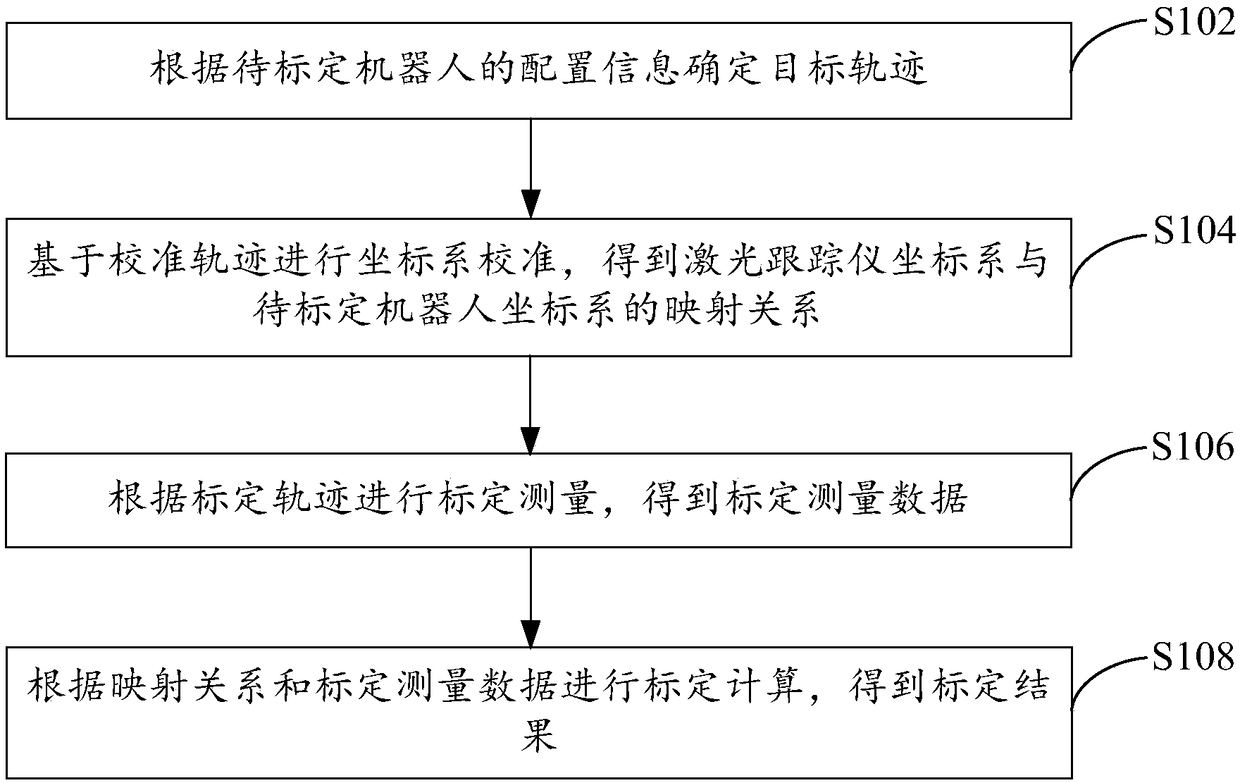
[0067] An optimized robot calibration method, applied to the test system software, the test system software is set on the terminal equipment, refer to figure 1 , the method includes:

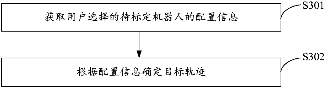
[0068] S102. Determine the target trajectory according to the configuration information of the robot to be calibrated, wherein the target trajectory includes: a calibration trajectory, a calibration trajectory;

[0069] In the embodiment of the present invention, the execution subject of the optimized robot calibration method is the test system software, and the test system software is installed on the terminal device. Specifically, the terminal device may be a computer.

[0070] The test system software in the present invention can determine the target trajectory according to the configuration information of the robot to be calibrated without user-defined trajectory. The specific content will be described below and will not be repeated here.

[0071] S104. Calibrate the coordinate system base...

Embodiment 2

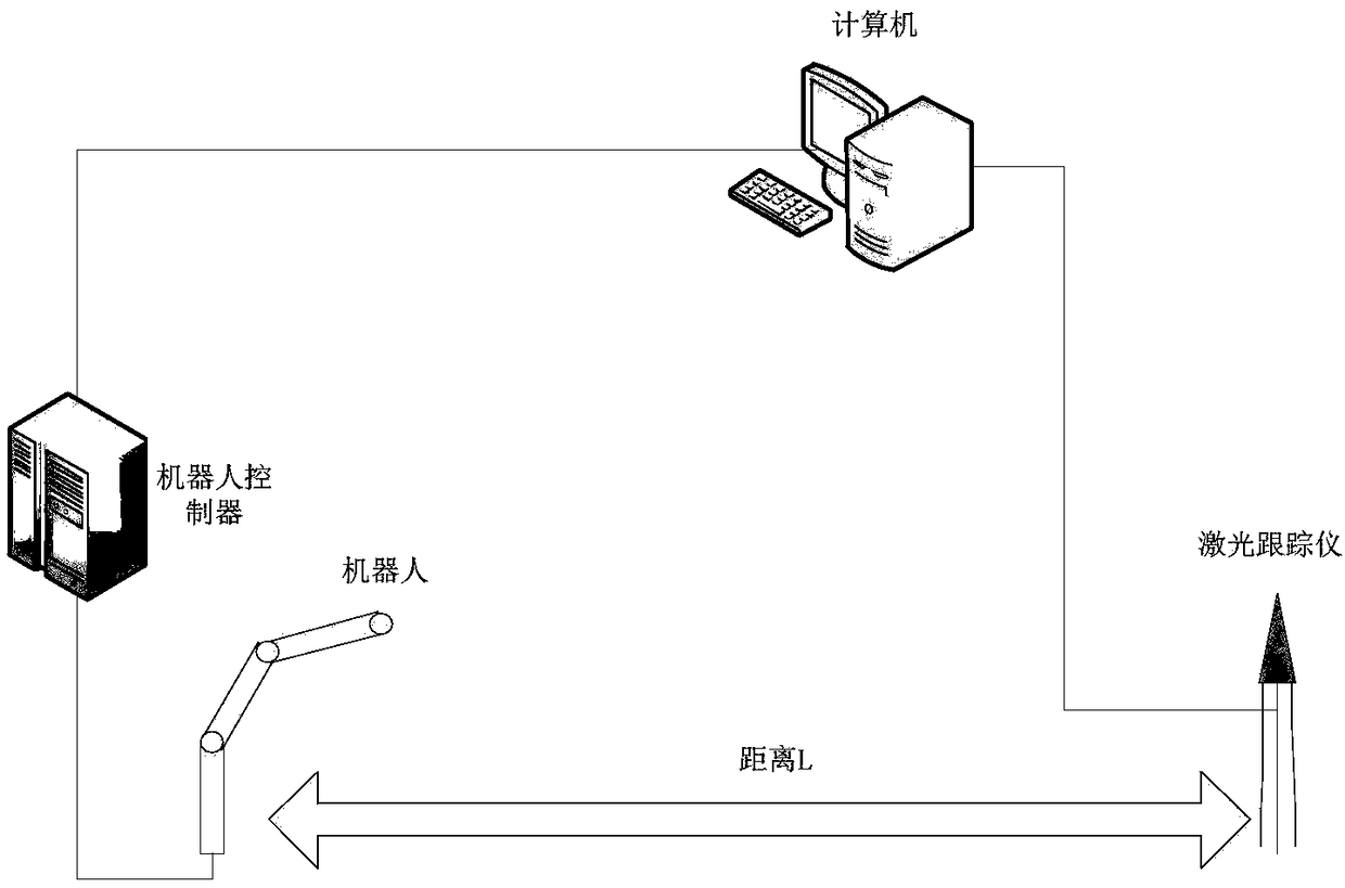
[0141] An optimized robot calibration device, the device is set on the terminal equipment, refer to Figure 7 , the device consists of:

[0142] Determining module 11, is used for determining target track according to the configuration information of robot to be calibrated, and wherein, target track comprises: calibration track, calibration track;

[0143] The coordinate system calibration module 12 is used to calibrate the coordinate system based on the calibration trajectory to obtain the mapping relationship between the laser tracker coordinate system and the robot coordinate system to be calibrated;

[0144] The calibration measurement module 13 is used to perform calibration measurement according to the calibration trajectory to obtain calibration measurement data, wherein the calibration measurement data includes: the end coordinates of the robot to be calibrated, the attitude angle of the robot to be calibrated, and the target ball coordinates measured by the laser trac...


PUM


Abstract

The invention provides an optimized robot calibration method and device. The optimized robot calibration method comprises the following steps that a target trajectory is determined according to configuration information of a to-be-calibrated robot; calibrating of a coordinate system is conducted based on a standardizing trajectory, and a mapping relationship of a laser tracker coordinate system and a to-be-calibrated robot coordinate system is obtained; calibration measurement is conducted according to a calibration trajectory, and calibration measurement data are obtained; and calibration calculation is conducted according to the mapping relationship and the calibration measurement data, and calibration results are obtained. According to the optimized robot calibration method, the standardizing trajectory and the calibration trajectory can be provided for users, custom setting of the users is not required, the calibration results can be automatically calculated, the to-be-calibrated robot and a laser tracker can be controlled simultaneously through test system software, operation is easy, the technical requirement for the users is reduced, the calibration efficiency is improved, and the technical problems that an existing robot calibration method is complex in operation, high in requirement for testers and low in efficiency are relieved.

Description

technical field [0001] The invention relates to the technical field of robot calibration, in particular to an optimized robot calibration method and device. Background technique [0002] The robot is the core equipment of modern production. According to the relevant regulations, the robot needs to be calibrated and performance tested before leaving the factory or after a long period of use to ensure that the accuracy and performance of the robot meet the requirements. In the current common method of using a laser tracker to calibrate and test the robot, each test cycle needs to manually point the laser tracker to the target ball. After the light is successfully tracked, run the robot and start measurement. [0003] Existing methods generally need to manually set the test pose, manually save the original data, customize the calibration trajectory, manually calculate the calibration results, and repeatedly switch between the robot system and the laser tracker system. The opera...

Claims


Application Information

Patent Timeline
Patent Type & Authority Applications(China)
IPC IPC(8): B25J9/16B25J19/00
CPCB25J9/1692B25J19/0095
Inventor 杨跞谭龙山周飞
Owner SIASUN CO LTD
Why Eureka
Try Eureka