Circuit board processing device
A processing device and circuit board technology, applied in metal processing and other directions, can solve the problems of inability to automatically rotate the circuit board, hand cuts, and low cutting efficiency.
- Summary
- Abstract
- Description
- Claims
- Application Information
AI Technical Summary
Problems solved by technology
Method used
Image
Examples
Embodiment Construction
[0014] The following is further described in detail through specific implementation methods:
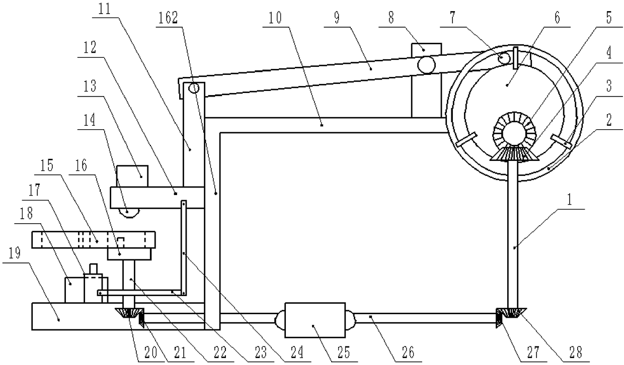
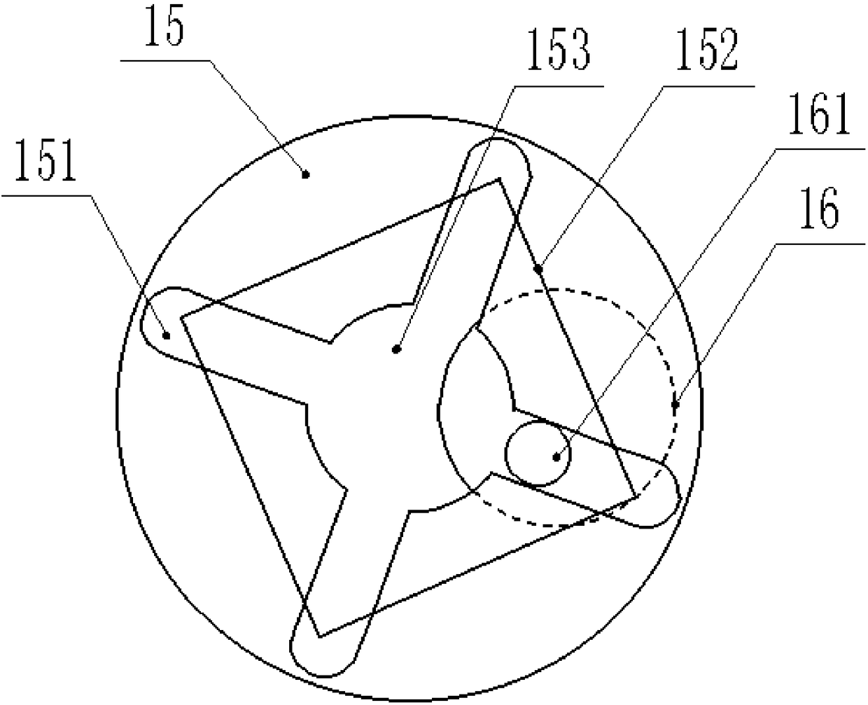
[0015] The reference signs in the drawings of the description include: shaft 1, ring 2, connecting piece 3, third bevel gear 4, fourth bevel gear 5, disc 6, pin shaft 7, vertical plate 8, lever 9, horizontal plate 10. Transmission rod 11, cutting plate 12, cutting motor 13, cutting tool 14, rotating disk 15, long hole 151, placement groove 152, through hole 153, dial 16, lever 161, slide rail 162, jack 17 , collection box 18, base 19, fifth bevel gear 20, sixth bevel gear 21, vertical shaft 22, pressure bar 23, connecting rod 24, motor 25, first output shaft 26, first bevel gear 27, second bevel gear gear 28.
[0016] The embodiment is basically as attached Figure 1-Figure 2 Shown: a circuit board processing device, including a frame, the frame includes a base 19, a horizontal plate 10 and a vertical slide rail 162, the horizontal plate 10 is located above the right side of the ba...
PUM
 Abstract
Description
Claims
Application Information
 - R&D
- Intellectual Property
- Life Sciences
- Materials
- Tech Scout
- Unparalleled Data Quality
- Higher Quality Content
- 60% Fewer Hallucinations
Browse by: Latest US Patents, China's latest patents, Technical Efficacy Thesaurus, Application Domain, Technology Topic, Popular Technical Reports.
© 2025 PatSnap. All rights reserved.Legal|Privacy policy|Modern Slavery Act Transparency Statement|Sitemap|About US| Contact US: help@patsnap.com


