
Pneumatic tire

A pneumatic tire, tire circumferential technology, applied to tire parts, tire tread/tread pattern, transportation and packaging, etc., can solve insufficient problems, improve drainage, improve partial wear resistance and straight travel sexual effect

Active Publication Date: 2018-06-15
TOYO TIRE & RUBBER CO LTD
View PDF9 Cites 2 Cited by
  • Summary
  • Abstract
  • Description
  • Claims
  • Application Information

AI Technical Summary

Problems solved by technology

[0003] However, in the above-mentioned conventional structure, although effective water drainage from the tread surface (wet performance), uneven wear resistance of the blocks, and straight running performance of the tire are taken into consideration, they are not sufficient.

Method used


Image

  • Pneumatic tire
  • Pneumatic tire

Examples


Embodiment Construction

[0034] Hereinafter, embodiments according to the present invention will be described with reference to the drawings. In addition, the following description is merely an example in nature, and is not intended to limit the present invention, its application, or its use. In addition, the drawings are schematic diagrams, and ratios of dimensions and the like are different from actual ratios of dimensions.

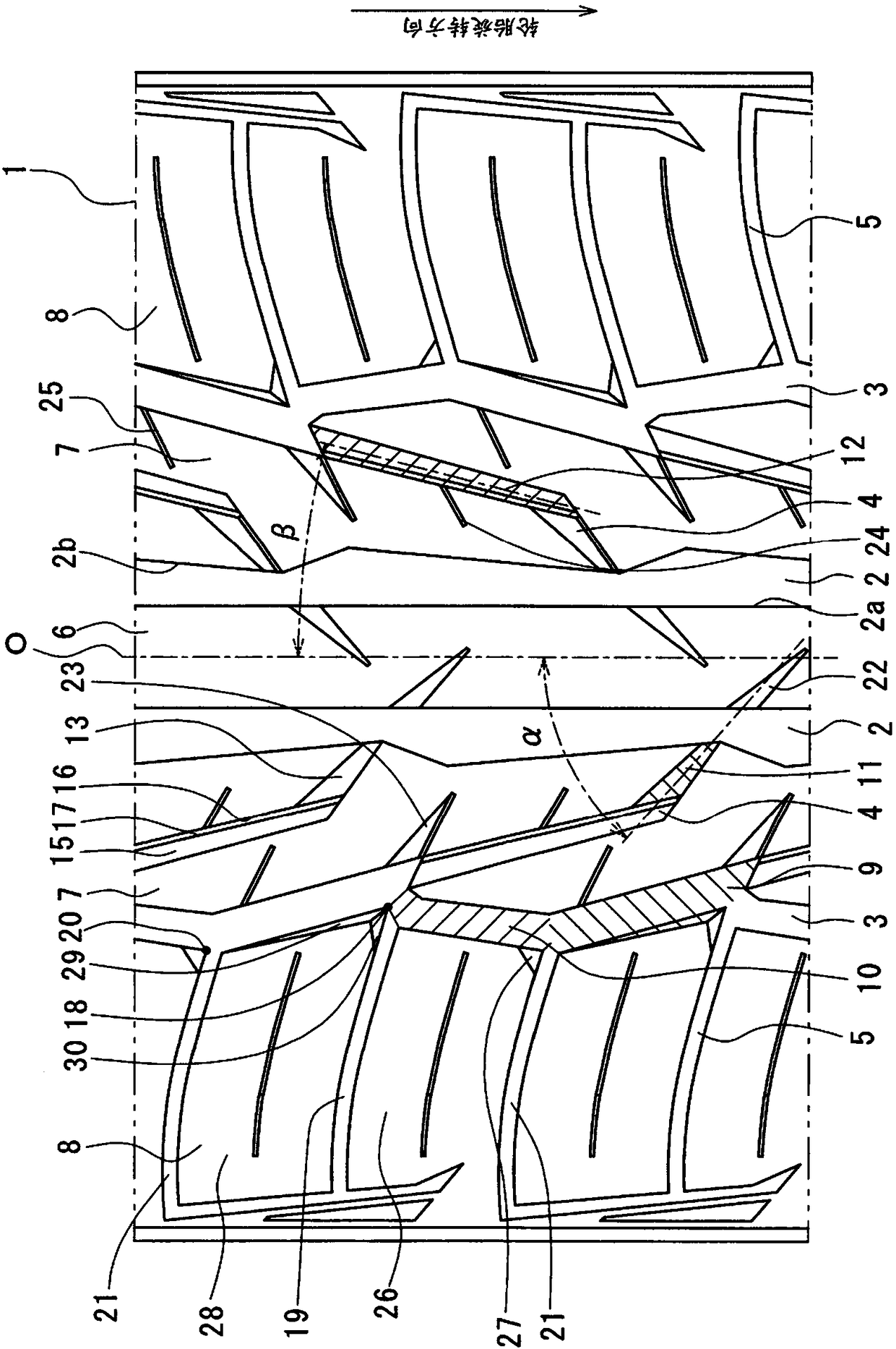
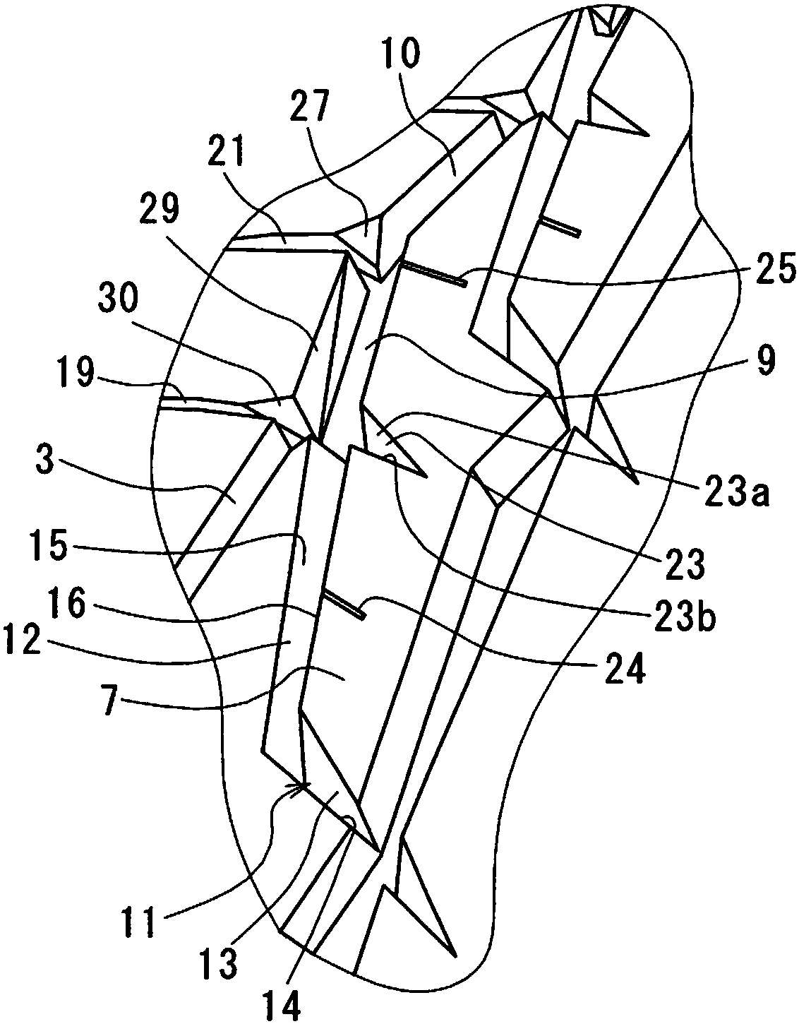
[0035] figure 1 It is a partially developed view of the tread surface 1 of the pneumatic tire according to the present embodiment, figure 2 is its partially enlarged perspective view. Through the center main groove 2, the shoulder main groove 3, the inclined groove 4, and the shoulder lateral groove 5, the land portion, that is, the center rib 6, the middle block 7, and the shoulder pattern are formed on the tread surface 1. Block 8. figure 1 The up and down direction is the tire circumferential direction, and the left and right direction is the tire width direction.

[0...


PUM


Abstract

The invention provides a pneumatic tire which can exhibit excellent performances in all of wet property, uneven wear resistance and straight traveling performance of the tire. A pneumatic tire comprises on a tread surface (1) thereof: a center main groove (2) extending in a tire circumferential direction; a shoulder main groove (3) extending in the tire circumferential direction at a position awayfrom the center main groove (2) in a tire width direction; and inclined grooves (4) formed at predetermined intervals in the tire circumferential direction, wherein each inclined groove includes a first inclined portion (11) extending from the center main groove (2) toward the shoulder main groove (3) while increasing a width thereof, the first inclined portion 11 extending at a first angle alphawith respect to the tire circumferential direction, and a second inclined portion (12) continuously formed with the first inclined portion, the second inclined portion (12) extending at a second angle beta smaller than the first angle alpha with respect to the tire circumferential direction.

Description

technical field [0001] The present invention relates to pneumatic tires. Background technique [0002] Conventionally, as a pneumatic tire, inclined grooves are provided on the tread surface. In this pneumatic tire, the inclined wall portion constituting the inclined groove is inclined at an acute angle with respect to the surface of the land portion (see, for example, Patent Document 1). [0003] However, in the above-mentioned conventional structure, although effective water drainage from the tread surface (wet performance), partial wear resistance of the blocks, and straightness of the tire are taken into consideration, they are not sufficient. [0004] patent documents [0005] Patent Document 1: Japanese Unexamined Patent Publication No. 2007-112218 Contents of the invention [0006] The object of the present invention is to provide a pneumatic tire that exhibits unprecedented excellent effects in all of wet performance, uneven wear resistance, and straight running...

Claims


Application Information

Patent Timeline
Patent Type & Authority Applications(China)
IPC IPC(8): B60C11/03B60C11/12
CPCB60C11/032B60C11/1236B60C2011/0374B60C11/1384B60C2011/0388B60C2011/0346B60C2011/0383B60C2011/1254B60C11/0302B60C11/1307
Inventor 佐野伸悟
Owner TOYO TIRE & RUBBER CO LTD
Learn More