Automatic casting blank lifting roller way system and application method thereof

A roller table system and automatic lifting technology, which is applied in the direction of hoisting devices, lifting equipment safety devices, etc., can solve the problems such as the inability to realize the raising and lowering of casting slabs, and achieve the effects of ensuring the level, avoiding unbalanced load, and accurate positioning

Active Publication Date: 2018-06-15
CHINA NAT HEAVY MACHINERY RES INSTCO
View PDF6 Cites 1 Cited by
  • Summary
  • Abstract
  • Description
  • Claims
  • Application Information

AI Technical Summary

Problems solved by technology

[0003] The purpose of the present invention is to provide a slab automatic lifting roller system and its application method, the purpose is to overcome that the existing slab lifting system cannot realize the casting slab lifting with a super large height difference of more than 2 meters

Method used


Image

  • Automatic casting blank lifting roller way system and application method thereof
  • Automatic casting blank lifting roller way system and application method thereof
  • Automatic casting blank lifting roller way system and application method thereof

Examples


Embodiment 1

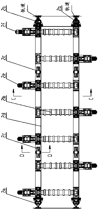
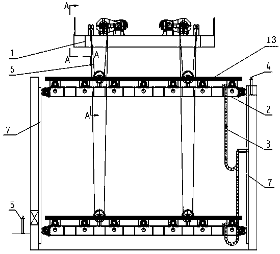
[0044] In order to solve the problem that the existing slab lifting system cannot realize the lifting and lowering of the slab with a super large height difference of more than 2 meters, this embodiment provides a slab automatic lifting roller table system, such as figure 1 and figure 2 , image 3 As shown, it includes the lifting device 1 fixed on the upper foundation 8. The lifting roller table 2 sliding up and down along the track 7 is suspended below the lifting device 1 through the wire rope 6. The lifting roller table 2 is used to carry the billet, receive and transport the casting Blank, the entrance side of the lifting roller table 2 is provided with a photoelectric switch 1 4 installed on the top of the lower foundation 9, and the outlet side is provided with a photoelectric switch 2 5 installed at the bottom of the lower foundation 9; as Figure 7 , Figure 8 and Figure 9As shown, the lifting roller table 2 includes a guide wheel 2a, a roller 2b, a pulley 2c, a ...

Embodiment 2

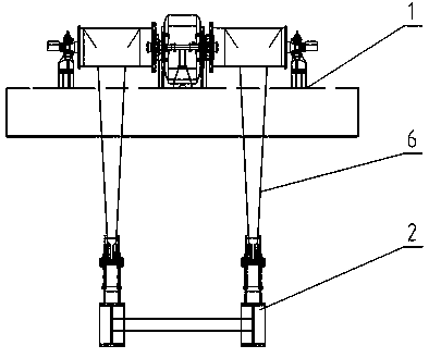
[0049] On the basis of Example 1, such as Figure 4 , Figure 5 and Figure 6 As shown, the lifting device 1 includes a base 1k fixed on the upper foundation 8. Two sets of independent and symmetrical transmission systems are installed on the base 1k. Each transmission system includes a speed reducer 1e installed on the base 1k. The motor 1e is provided with two input shafts and two output shafts, one of which is connected to the motor 1c through a coupling, and the brake 1d is installed on the coupling and the other input shaft, and the two output shafts of the reducer 1e Each reel 1b is equipped with a balance arm 1a installed on the base 1k. One end of the wire rope 6 is connected to the balance arm 1a, and the other end is wound around the pulley 2c on the reel 1b.

[0050] Such as Figure 5 As shown, the motor 1c is connected to the base 1k through bolts, the reducer 1e is connected to the base 1k through bolts, the reducer 1e has two input shafts, both input shafts ar...

Embodiment 3

[0052] On the basis of Example 2, such as Figure 6 As shown, an absolute encoder 1g is installed at the tail of each reel 1b, a weight switch 1f installed on the base 1k is installed under the bearing seat of the reel 1b, and a load cell is also installed on the base 1k 1h. An overspeed protection switch and an incremental encoder are installed at the tail of the motor 1c.

[0053] In the lifting device 1, four absolute value encoders 1g are respectively assembled at the tails of the four sets of reels 1b, and the reading of the absolute value encoders 1g can realize the control of the lifting position and speed of the lifting roller table 1; the weight switch 1f is passed through the bolt It is connected to the base 1k, when the lifting roller table 2 rises to a certain height, the weight switch 1f is triggered, and the lifting device 1 stops; the load cell 1h is respectively installed under the bearing seat, connected to the base 1k by bolts, and passed by the load cell 1h...


PUM


Abstract

The invention provides an automatic casting blank lifting roller way system and an application method thereof. The system comprises a lifting device, a lifting roller way sliding up and down along a rail is hung below the lifting device, the lifting roller way comprises four sets of guide wheels, the guide wheels are arranged at the four ends of the support, and can slide in the rail, multiple rollers are evenly distributed on a support at intervals along the straight line, a speed reduction motor is arranged at one end of each roller, an encoder is arranged on the tail of the first speed reduction motor on the inlet side of the lifting roller way, four hanging points are arranged on the support, a pulley is arranged on each hanging point, the lifting device is controlled to ascend and descend in a manner that four sets of steel wire ropes are wound on the four sets of pulleys. According to the system, a casting blank with the super-large height difference larger than two meters is automatically lifted and transported, automatic transportation of the casting blank from high to low is solved, automatic transportation of the casting blank from low to high is achieved, and automatic slab transportation from low to high is the inverse process from high to low.

Description

technical field [0001] The invention belongs to the field of metallurgy, and in particular relates to an automatic lifting roller table system for casting slabs, in particular to an automatic lifting roller table system for casting slabs capable of realizing a super large height difference and an application method thereof. Background technique [0002] At present, billet lifting systems at home and abroad are divided into billet lifting systems and billet lifting systems. For the billet lifting system, due to the small section of the billet and the light weight of a single billet, the motor drive and chain transmission structure are generally used to realize the billet lifting system. Lifting of the slab; for the slab lifting system, due to the large section of the conventional slab and the heavy weight of a single piece (generally above 20 tons), the existing lifting system generally uses a hydraulic lifting system to realize the lifting of the slab, but the difference in l...

Claims


Application Information

Patent Timeline
Patent Type & Authority Applications(China)
IPC IPC(8): B66F11/00B66F17/00
CPCB66F11/00B66F17/00
Inventor 周士凯王蓉何博梅瑾烨
Owner CHINA NAT HEAVY MACHINERY RES INSTCO
Why Eureka
Try Eureka