Precision instrument guide rail system based on circular rolling element array arrangement and cambered surface clamping and positioning

A technology for clamping and positioning precision instruments, applied in the directions of instruments, measuring instrument components, bearings for linear motion, etc., it can solve the problems of inability to adjust the supporting force of the supporting surface, complex locking mechanism, low stiffness of the guide rail, etc., and achieve high motion accuracy. and stability, avoiding guide rail motion guide errors, and good bearing performance.

Active Publication Date: 2018-06-15
HARBIN INST OF TECH
View PDF10 Cites 1 Cited by
  • Summary
  • Abstract
  • Description
  • Claims
  • Application Information

AI Technical Summary

Problems solved by technology

[0007] Comprehensive analysis of the common problems existing in the existing technology is that the stiffness of the guide rail is low, the support force of the supporting surface cannot be adjusted, and the clamping method of the sensor on the guide rail is mostly a jackscrew or hinge structure, and the locking is not secure or locked. Institutions are too complex

Method used


Image

  • Precision instrument guide rail system based on circular rolling element array arrangement and cambered surface clamping and positioning
  • Precision instrument guide rail system based on circular rolling element array arrangement and cambered surface clamping and positioning
  • Precision instrument guide rail system based on circular rolling element array arrangement and cambered surface clamping and positioning

Examples


Embodiment Construction

[0031] Embodiments of the present invention will be described in detail below in conjunction with the accompanying drawings.

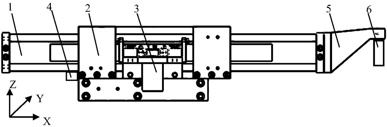
[0032] Depend on figure 1 As shown, the precision instrument rail system based on the array arrangement of circulating rolling elements and the clamping and positioning of the arc surface includes a rail component 1, a rail frame component 2, a driving component 3, a position detection component 4 and a sensor clamping and locking component 5; the driving component 3 Drive the guide rail part 1 to move back and forth along the X-axis direction in the guide rail frame part 2, and the sensor clamps the locking part 5 to lock the positioning sensor 6; the friction form between the guide rail part 1 and the guide rail frame part 2 is rolling friction .

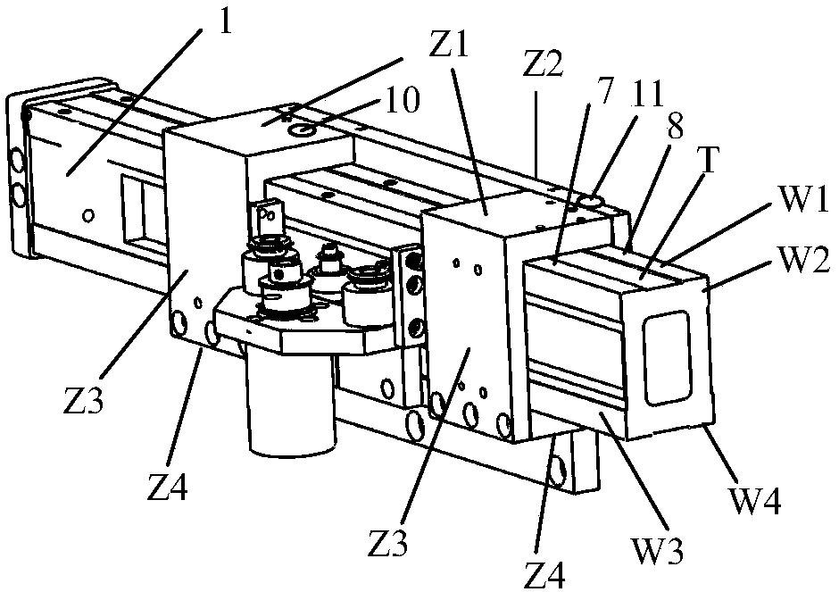
[0033] The guide rail component 1 is a cuboid structure with a rectangular cross section and four working surfaces, such as figure 2 As shown, it includes the first working surface W1, the second workin...


PUM


Abstract

The invention discloses a precision instrument guide rail system based on circular rolling element array arrangement and cambered surface clamping and positioning and belongs to the technical field ofprecision instruments and machines. A guide rail component is provided with four working faces, the middle area of each working face is of a groove structure, and each working face is symmetrically provided with two coplanar boss working belts of equal height. A guide rail rack component is composed of four supporting guide plates, and each supporting guide plate is provided with a rolling element set which comprises three rolling unit arrays distributed in a triangle mode. Each rolling unit array is formed by densely distributing a plurality of rolling elements. A sensor clamping and lockingcomponent comprises a clamping matrix, a clamping moving body and a clamping feeding mechanism; the clamping matrix is provided with a long-strip-shaped arc hole, a threaded hole and an arc groove; and the clamping moving body moves in the long-strip-shaped arc hole under the action of the clamping feeding mechanism so that a sensor can be locked or released. The precision instrument guide rail system integrates the characteristics of high precision, high rigidity and the clamping and locking features.

Description

technical field [0001] The invention belongs to the technical field of precision instruments and machinery, and in particular relates to a guide rail system for precision instruments based on the array arrangement of circulating rolling bodies and the clamping and positioning of arc surfaces. Background technique [0002] In the field of precision measurement, linear motion guidance and positioning accuracy, as one of the important performances of measuring instruments and systems, have a great impact on the reliability and accuracy of measurement results. Linear motion guide rails are an important part of precision measuring instruments. It directly affects and restricts the comprehensive performance of the instrument. [0003] In 2011, the China Metrology Institute conducted research on the precise positioning and synchronization of the coaxial double-drive guideway. The coaxial double-drive guideway is a structure adopted for a specific measurement system, which is a comb...

Claims


Application Information

Patent Timeline
Patent Type & Authority Applications(China)
IPC IPC(8): F16C29/06G01D11/16
CPCF16C29/005F16C29/008F16C29/0604F16C29/0614G01D11/16
Inventor 黄景志郑惠馨谭久彬
Owner HARBIN INST OF TECH
Why Eureka
Try Eureka