
Pumping unit brake assembly

A pumping unit and assembly technology, which is applied in the field of pumping unit brake assembly, can solve the problems of difficult pumping unit shutdown attitude adjustment again, difficult adjustment of pumping unit shutdown attitude, poor attitude adjustment accuracy, etc., to achieve saving Remove the brake safety device, avoid the car from slipping, and ensure the effectiveness of the effect

Active Publication Date: 2018-06-15
DAQING TIANDEZHONG PETROLEUM SCI & TECH CO LTD
View PDF9 Cites 3 Cited by
  • Summary
  • Abstract
  • Description
  • Claims
  • Application Information

AI Technical Summary

Problems solved by technology

However, there are obvious defects in this braking device: 1. When the pumping unit is overhauled, it is often necessary to adjust the main transmission mechanism of the pumping unit to a plurality of different position states, so that the pumping unit is fully maintained and checked, and After the brake shaft is locked by the above-mentioned brake device, it is difficult to adjust the stop posture of the pumping unit again. If the stop posture is adjusted again, the pumping unit can only be started again after the brake is released, and then brake again at the right time , the operation is very cumbersome and the accuracy of attitude adjustment is very poor. In addition, when the motor of the pumping unit fails, the stop attitude of the pumping unit is more difficult to adjust; 2. The inside of the clamp arm and the outside of the brake wheel of the existing brake device are both It is a flat circular arc surface, because the smooth circular arc friction surface has hidden dangers of slipping, so the brake device must be additionally equipped with a brake safety device

Method used


Image

  • Pumping unit brake assembly
  • Pumping unit brake assembly
  • Pumping unit brake assembly

Examples


Embodiment Construction

[0017] The present invention will be further described below in conjunction with accompanying drawing:

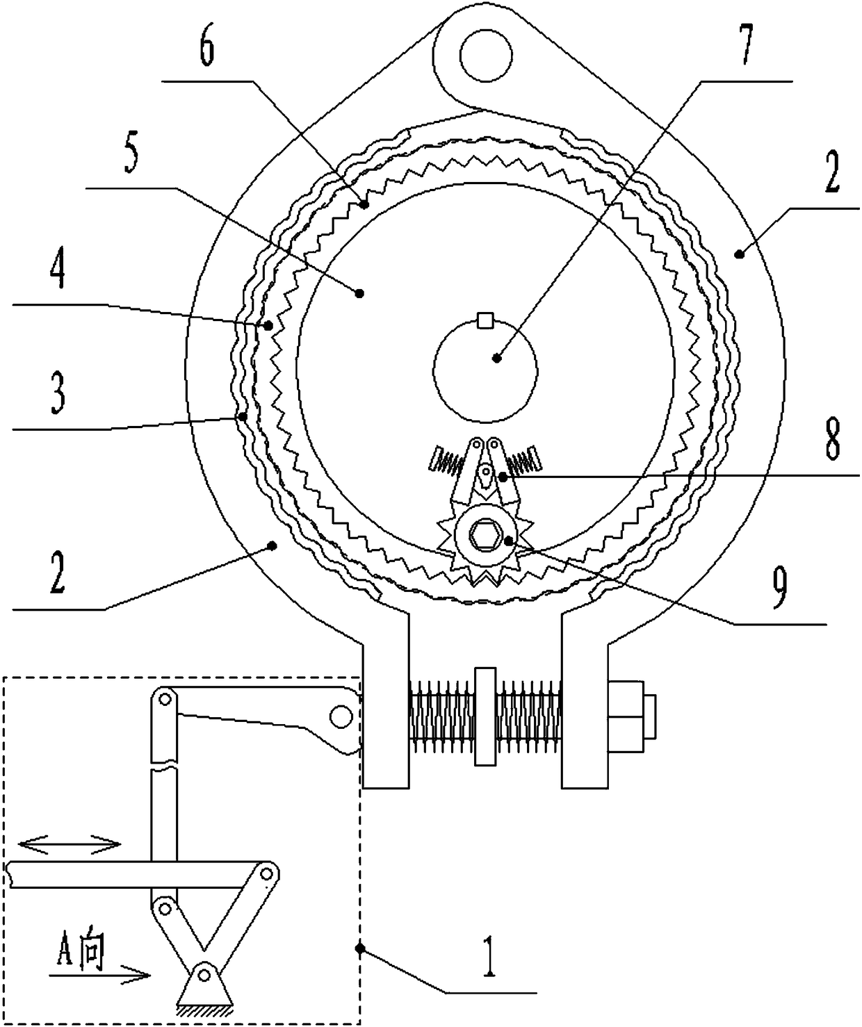
[0018] The present invention includes a brake unit and a link control mechanism 1, the brake unit is provided with a brake wheel and a clamp arm 2, the brake wheel is fixedly installed on the brake shaft 7 that needs to be braked, and there are two clamp arms 2 , the two clamp arms 2 are hingedly connected to form a ring structure with an opening, and the inner side of the clamp arm 2 is fixed with a brake pad 3. When braking, the two clamp arms 2 will brake from the outside under the drive of the linkage control mechanism 1. The wheel is locked to achieve the braking of the brake wheel, that is, the braking of the pumping unit. The above are common structures in the prior art, and will not be repeated here.

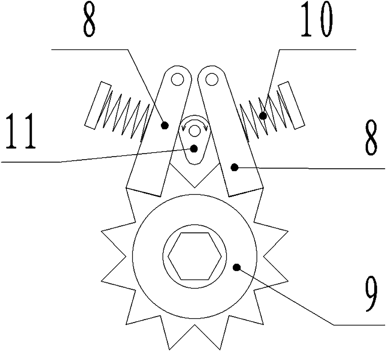
[0019] The brake wheel is divided into inner ring 5 and outer ring 4. The outer ring 4 is sleeved on the inner ring 5 and can rotate around the axis of the inner rin...


PUM


Abstract

The invention belongs to the field of pumping unit accessories, and particularly relates to a pumping unit brake assembly. The brake assembly comprises a brake unit and a connecting rod control mechanism, wherein a brake wheel and clamp arms are arranged in the brake unit, and the brake wheel is fixedly installed on a brake shaft needing braking; the number of the clamping arms is two, and two clamping arms are hinged to form a circular ring structure with an opening; and the brake wheel is divided into an inner ring and an outer ring, wherein the outer ring sleeves the inner ring and can rotate around the axis of the inner ring, the inner ring is fixedly installed on the brake shaft, a gear is installed on the edge of the side surface of the inner ring, wheel teeth meshed with the gear are arranged on the inner side of the outer ring, and the side surface of the inner ring is further provided with a two-way check assembly used for clamping the gear. According to the pumping unit brakeassembly, in the braking state, the gear is driven to rotate through a spanner, the brake shaft can be rotated under the condition that the braking state is kept unchanged, so that the shutdown posture of the pumping unit is adjusted, and therefore great convenience is provided for maintenance and inspection of the pumping unit.

Description

technical field [0001] The invention belongs to the field of pumping unit accessories, in particular to a brake assembly of a pumping unit. Background technique [0002] The beam pumping unit is the most common oil extraction equipment. The beam pumping unit is equipped with a brake device, which is used to brake the pumping unit when the pumping unit is shut down for maintenance to prevent the pumping unit from being damaged. Controlled operation poses safety hazards. The structure of the brake device on the beam pumping unit usually includes a brake wheel, a clamp arm and a link control mechanism. The brake wheel is fixed on the brake shaft on the reduction box, and the clamp arm is driven from the outside by the link control mechanism Lock the brake wheel to realize braking. However, there are obvious defects in this braking device: 1. When the pumping unit is overhauled, it is often necessary to adjust the main transmission mechanism of the pumping unit to a plurality ...

Claims


Application Information

Patent Timeline
IPC IPC(8): F16D49/16F16D65/06F16D69/00F16D65/14F16D121/14
CPCF16D49/16F16D65/06F16D65/14F16D69/00F16D2121/14
Inventor 张淞源张虎
Owner DAQING TIANDEZHONG PETROLEUM SCI & TECH CO LTD
Learn More