Method for improving automatic driving reliability and electronic equipment
An autonomous driving and reliability technology, applied in the direction of TV, color TV, electrical components, etc., can solve the problems of affecting the accuracy of sensors, unable to perceive obstacles normally, and locate hidden dangers of vehicles, so as to eliminate hidden dangers and improve reliability. Effect
- Summary
- Abstract
- Description
- Claims
- Application Information
AI Technical Summary
Problems solved by technology
Method used
Image

Examples
Embodiment 1
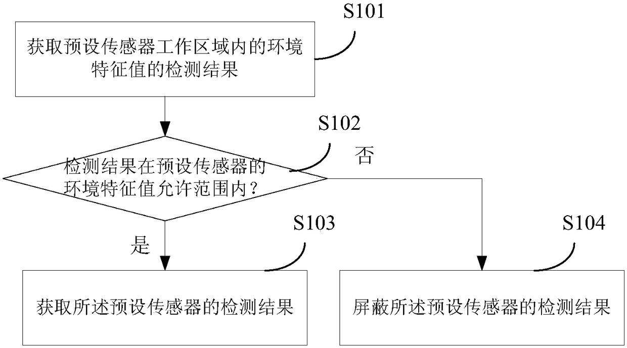
[0039] This embodiment provides a method for improving the reliability of automatic driving, which is applied to the automatic driving system of the vehicle, such as figure 1 shown, including the following steps:
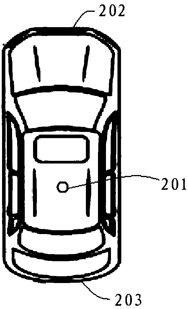
[0040] S101: Obtain a detection result of an environmental feature value within a preset sensor working area. Wherein the preset sensors are used to provide data detection during the automatic driving process, such as distance sensors, speed sensors, lidar and cameras. For each sensor it has a corresponding working area. by figure 2 Taking the car shown as an example, the lidar 201 is installed on the top of the lidar. The working area of the lidar is centered on its installation position, and can be detected within a 360-degree range. The detection distance can be determined according to different configurations of the lidar. The front and rear of the car are fixed with cameras 202 and 203. For the front camera 202, its working area is within 180 degrees of t...
Embodiment 2
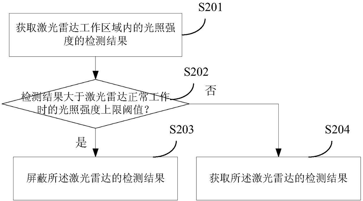
[0047] On the basis of Embodiment 1, the preset sensor in this embodiment is a laser radar, and the environmental feature value includes light intensity, and its specific implementation method is as follows image 3 Shown:
[0048]S201: Obtain a detection result of the light intensity in the lidar working area. The working area of the lidar is the 360-degree range around the installation position of the lidar.
[0049] S202: Determine whether the detection result of the light intensity is greater than the upper limit threshold of the light intensity when the lidar works normally, and if so, perform step S203, otherwise, perform step S204.
[0050] S203: Shield the detection result of the lidar.
[0051] S204: Obtain a detection result of the lidar.
[0052] Because the detection results of the lidar are greatly affected by the light intensity, when the light intensity is too high, it may cause the wrong measurement of the lidar, so the upper limit threshold of the light i...
Embodiment 3
[0054] and image 3 The solutions shown are similar. In this embodiment, the preset sensor can also be a camera, and the environmental characteristic value includes light intensity, and its specific implementation method is as follows Figure 4 Shown:
[0055] S301: Obtain the detection result of the light intensity in the working area of the camera, where the working area of the camera is the area covered by the shooting angle of view.
[0056] S302: Determine whether the detection result of the light intensity is greater than the upper limit threshold of the light intensity when the camera works normally, if so, perform step S305, otherwise, perform step S303.
[0057] S303: Determine whether the detection result of the light intensity is less than the lower limit threshold of the light intensity when the camera works normally, if so, perform step S305, otherwise, perform step S304.
[0058] S304: Obtain a detection result of the camera.
[0059] S305: Shield the dete...
PUM
 Abstract
Description
Claims
Application Information
PatSnap Eureka turns technology decisions into work you can execute. Powered by our Innovation Knowledge Graph, it runs expert workflows across engineering, life sciences, materials and intellectual property. Get your review-ready output in minutes.


