Lighting device and projection device

A lighting device and projection device technology, applied in the field of projection, can solve problems such as loss of field of view

Inactive Publication Date: 2018-06-15
JOURNEY TECH LTD
View PDF4 Cites 1 Cited by
  • Summary
  • Abstract
  • Description
  • Claims
  • Application Information

AI Technical Summary

Problems solved by technology

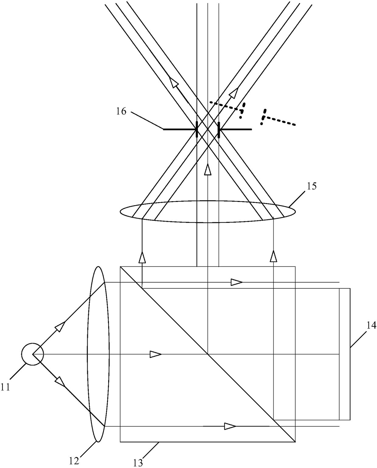
But when the human eye is dynamic, when the human eye pupil 16 is shifted to figure 1 When the dotted line position in , it will cause the loss of field of view

Method used


Image

  • Lighting device and projection device
  • Lighting device and projection device
  • Lighting device and projection device

Examples


Embodiment Construction

[0025] The following description and drawings illustrate specific embodiments of the invention sufficiently to enable those skilled in the art to practice them. The examples merely represent possible variations. Individual components and functions are optional unless explicitly required, and the order of operations may vary. Portions and features of some embodiments may be included in or substituted for those of other embodiments. The scope of embodiments of the present invention includes the full scope of the claims, and all available equivalents of the claims. Herein, various embodiments may be referred to individually or collectively by the term "invention", which is for convenience only and is not intended to automatically limit the scope of this application if in fact more than one invention is disclosed. A single invention or inventive concept. Herein, relational terms such as first and second etc. are used only to distinguish one entity or operation from another with...


PUM


Abstract

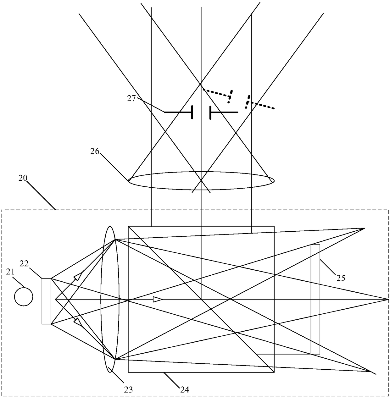
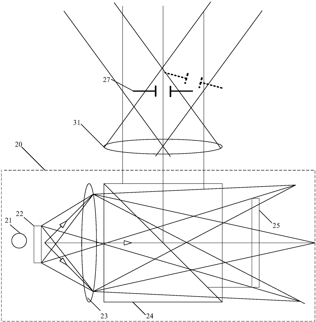
The invention provides a lighting device and a projection device. The lighting device is composed of a light source, a light homogenizer, an illumination lens, a polarizing beam-splitter (PBS), and asilicon-based liquid crystal LCoS. The light homogenizer is arranged between the light source and the illumination lens. With the light homogenizer, large-angle-range illumination light is provided for each pixel on LCos, so that the light beam projected by the projection eye lens is widened and thus the pupil of the human eye is covered by the full field of view.

Description

technical field [0001] The invention relates to the projection field, in particular to an illuminating device and a projection device. Background technique [0002] Micro-projectors based on Liquid Crystal on Silicon (LCoS) technology are relatively mature technologies. As a wearable device, augmented reality (Augmented Reality, AR) glasses must have miniature components, so a micro-projector based on LCoS is a better image source for AR glasses. Generally, the receiving surface of a projector is a screen with diffuse reflection characteristics, while the receiving surface of AR glasses is the pupil of the human eye. The light angle at the pupil should be wide and uniform. If the angle of light entering the human eye is small, or the light intensity changes unevenly with the angle, the brightness of the image will change with the change of the angle of sight of the human eye, that is, the image is unstable in terms of visual perception. [0003] figure 1 It is a schemati...

Claims


Application Information

Patent Timeline
Patent Type & Authority Applications(China)
IPC IPC(8): G03B21/20
CPCG03B21/208
Inventor 刘健鹏
Owner JOURNEY TECH LTD
Why Eureka
Try Eureka