
Triggering drive circuit and organic luminescence display device

A driving circuit, an organic technology, applied in the direction of static indicators, instruments, etc., can solve the problems of uneven picture, unstable current, low driving current, etc.

Active Publication Date: 2018-06-15
NANJING CEC PANDA FPD TECH CO LTD
View PDF12 Cites 17 Cited by
  • Summary
  • Abstract
  • Description
  • Claims
  • Application Information

AI Technical Summary

Problems solved by technology

[0005] In order to solve the above technical problems, the present invention provides a trigger driving circuit and an organic light-emitting display device using the trigger driving circuit. The trigger driving circuit outputs a plurality of trigger driving signals with adjustable duty ratio and timing, and the trigger driving signal controls The time ratio of the organic light-emitting diodes in the organic light-emitting display device is bright and dark, so as to achieve the purpose of displaying different gray-scale images under the same current drive, and can avoid the problem caused by low driving current and unstable current when displaying low gray-scale. picture unevenness

Method used


Image

  • Triggering drive circuit and organic luminescence display device
  • Triggering drive circuit and organic luminescence display device
  • Triggering drive circuit and organic luminescence display device

Examples


Embodiment Construction

[0051] In order to more clearly illustrate the embodiments of the present invention or the technical solutions in the prior art, the specific implementation manners of the present invention will be described below with reference to the accompanying drawings. Obviously, the accompanying drawings in the following description are only some embodiments of the present invention, and those skilled in the art can obtain other accompanying drawings based on these drawings and obtain other implementations.

[0052] In order to make the drawing concise, each drawing only schematically shows the parts related to the present invention, and they do not represent the actual structure of the product. In addition, to make the drawings concise and easy to understand, in some drawings, only one of the components having the same structure or function is schematically shown, or only one of them is marked. Herein, "a" not only means "only one", but also means "more than one".

[0053] The struct...


PUM


Abstract

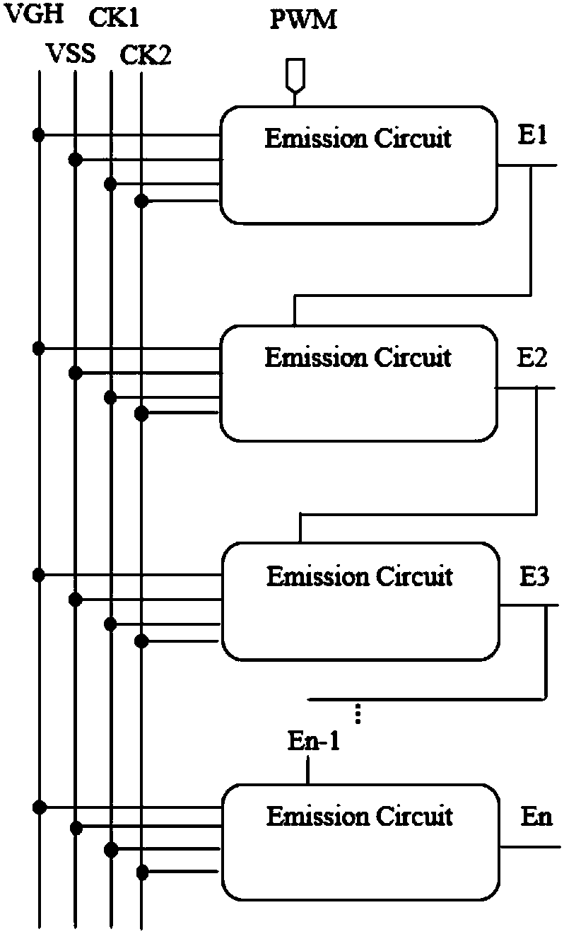
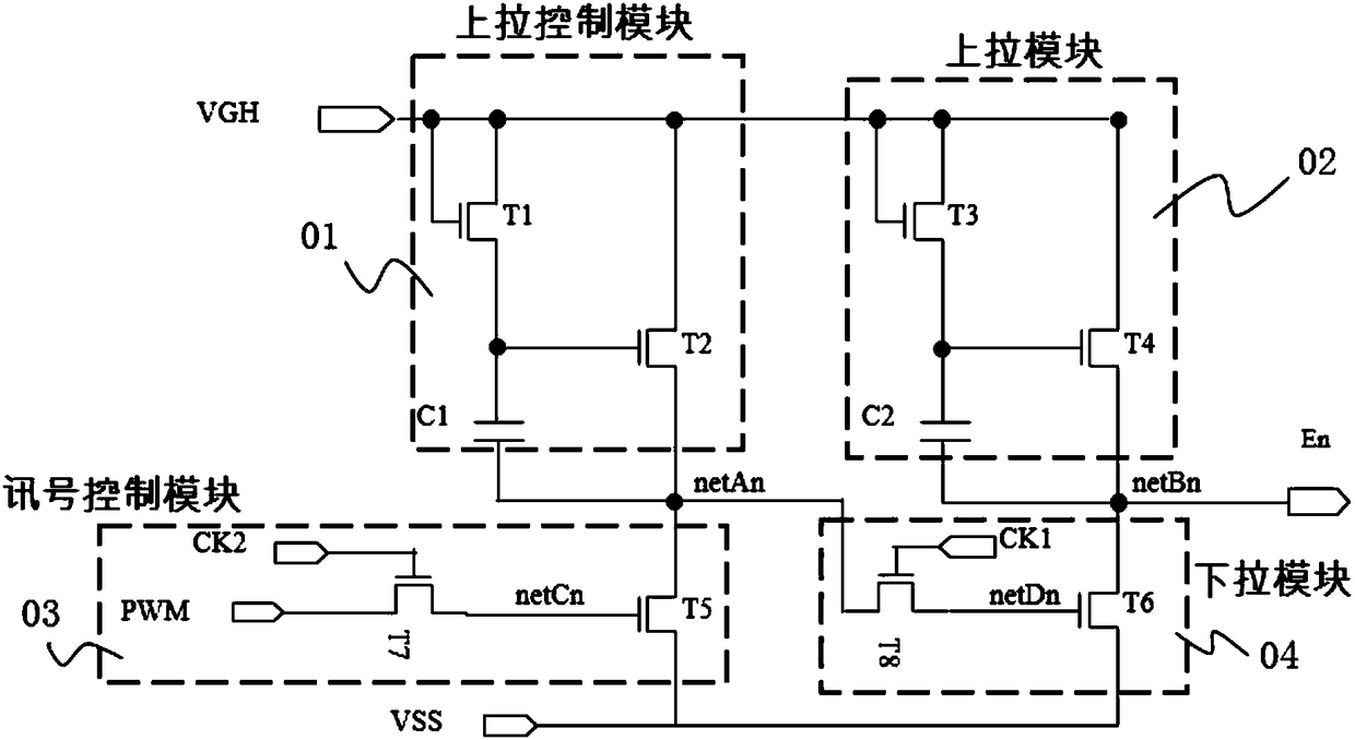
The present invention discloses a triggering drive circuit. The triggering drive circuit comprises N-level triggering drive circuit units (N>=2, and N is an integer); an nth-level triggering drive circuit unit comprises a pull-up control module, a pull-up module, a signal control module and a pull-down module, wherein 1<=n<=N, and n is an integer; and the pull-up control module, the pull-up moduleand the pull-down module are connected with a pull-up control node, the signal control module and the pull-down module are connected with an output node, and the output node outputs triggering drivesignals. The present invention further discloses an organic luminescence display device. The organic luminescence display device employs the triggering drive circuit to control a time proportion of brightness and darkness of an organic light emitting diode to achieve a function of displaying different gray-scale frames in the same current drive so that it is avoided that a drive current is low andthe current is unstable to cause an uniform frame problem when a low gray scale frame is displayed.

Description

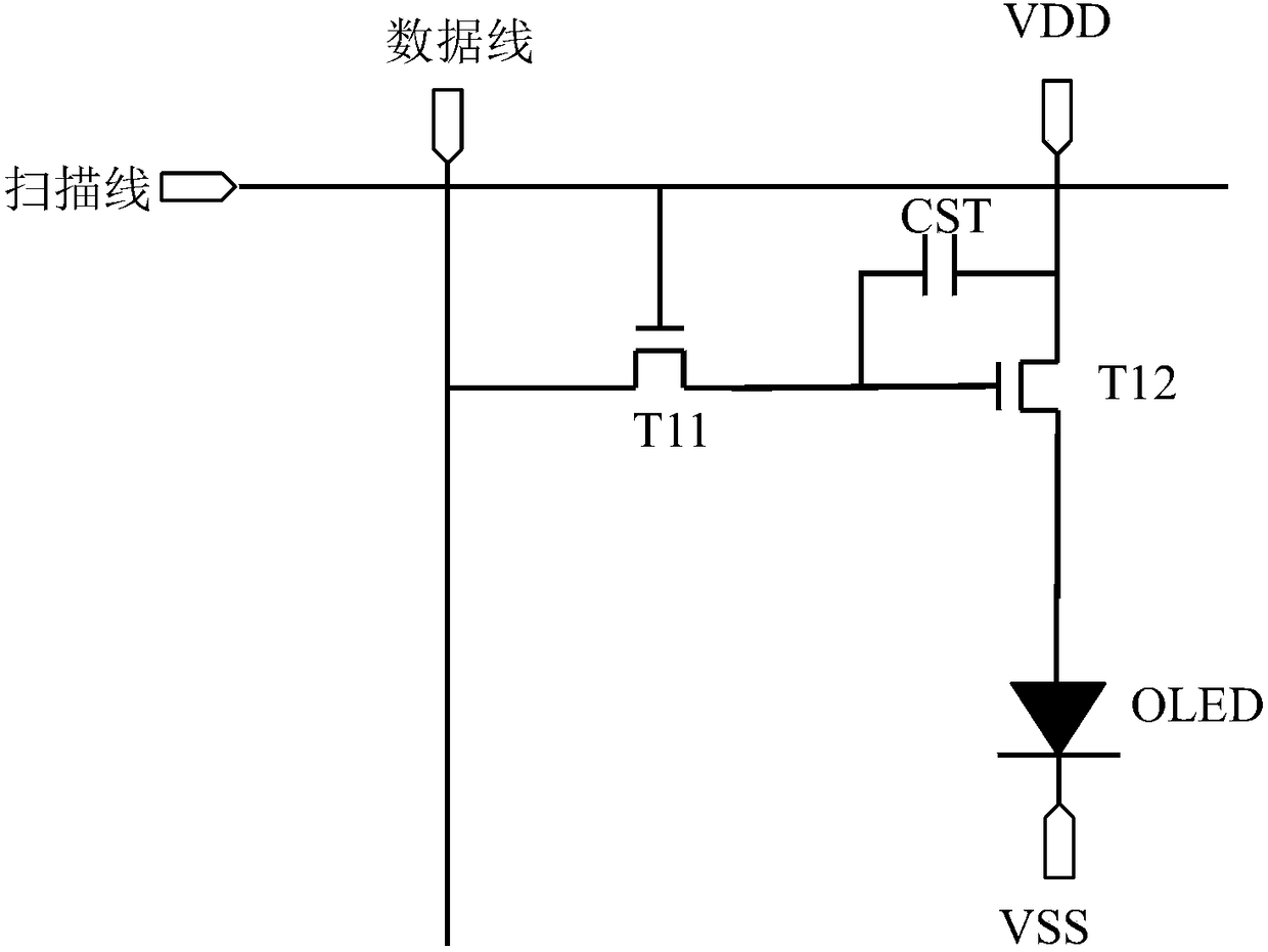
technical field [0001] The invention relates to the field of display technology, in particular to a trigger driving circuit and an organic light-emitting display device. Background technique [0002] The organic light emitting display device utilizes the advantages of high contrast ratio, high color gamut, wide viewing angle, low power consumption, and thinner and thinner brought by organic light emitting diodes (OLEDs), which are favored by the market. The principle of OLED light emission is briefly as follows: under the action of an external electric field, the electrons and holes provided by the cathode and anode are combined in the light-emitting layer to form excitons, and the excitons return to the ground state to emit photons. Therefore, OLED is a current light-emitting device. The circuit in the board controls the magnitude of the current, and then controls the brightness of the light. [0003] A prior art OLED drive circuit such as figure 1 As shown, the OLED driv...

Claims


Application Information

Patent Timeline
Patent Type & Authority Applications(China)
IPC IPC(8): G09G3/3225
CPCG09G3/3225
Inventor 赖谷皇戴超王志军
Owner NANJING CEC PANDA FPD TECH CO LTD
Learn More