Wireless power transfer system and transfer method

A technology of wireless power transmission and coils, applied in circuits, inductors, electrical components, etc., can solve problems such as energy consumption, wasting eigenmodes, and not making the best use of everything, and achieves simple operation, strong system stability, and high energy efficiency. Transfer Efficient Effects

Active Publication Date: 2018-06-15
TONGJI UNIV
View PDF5 Cites 4 Cited by
  • Summary
  • Abstract
  • Description
  • Claims
  • Application Information

AI Technical Summary

Problems solved by technology

However, although this solution can achieve efficient transmission of electric energy over a certain distance, it still cannot avoid the instability of the system under high power due to the diversity of circuit components.
In addition, the realization of two pure eigenmodes in the system also needs to provide an additional effective gain, but only one of them needs to be used for energy transmission; thus, there is an additional consumption of energy, and there is no exhaustion Its use wastes another eigenmode in the system
[0005] In summary, the use of non-radiative magnetic coupling coils for wireless power transmission is the current trend in this field, and the drop in transmission efficiency caused by near-field coupling mode splitting is also a major problem in this field.
At present, there is still no effective solution that can ensure the stability of the system's operating frequency and efficiency under the premise of changing transmission distances

Method used


Image

  • Wireless power transfer system and transfer method
  • Wireless power transfer system and transfer method
  • Wireless power transfer system and transfer method

Examples


Embodiment 1

[0049] Embodiment 1: A wireless power transfer system comprising a dual resonant coil arrangement.

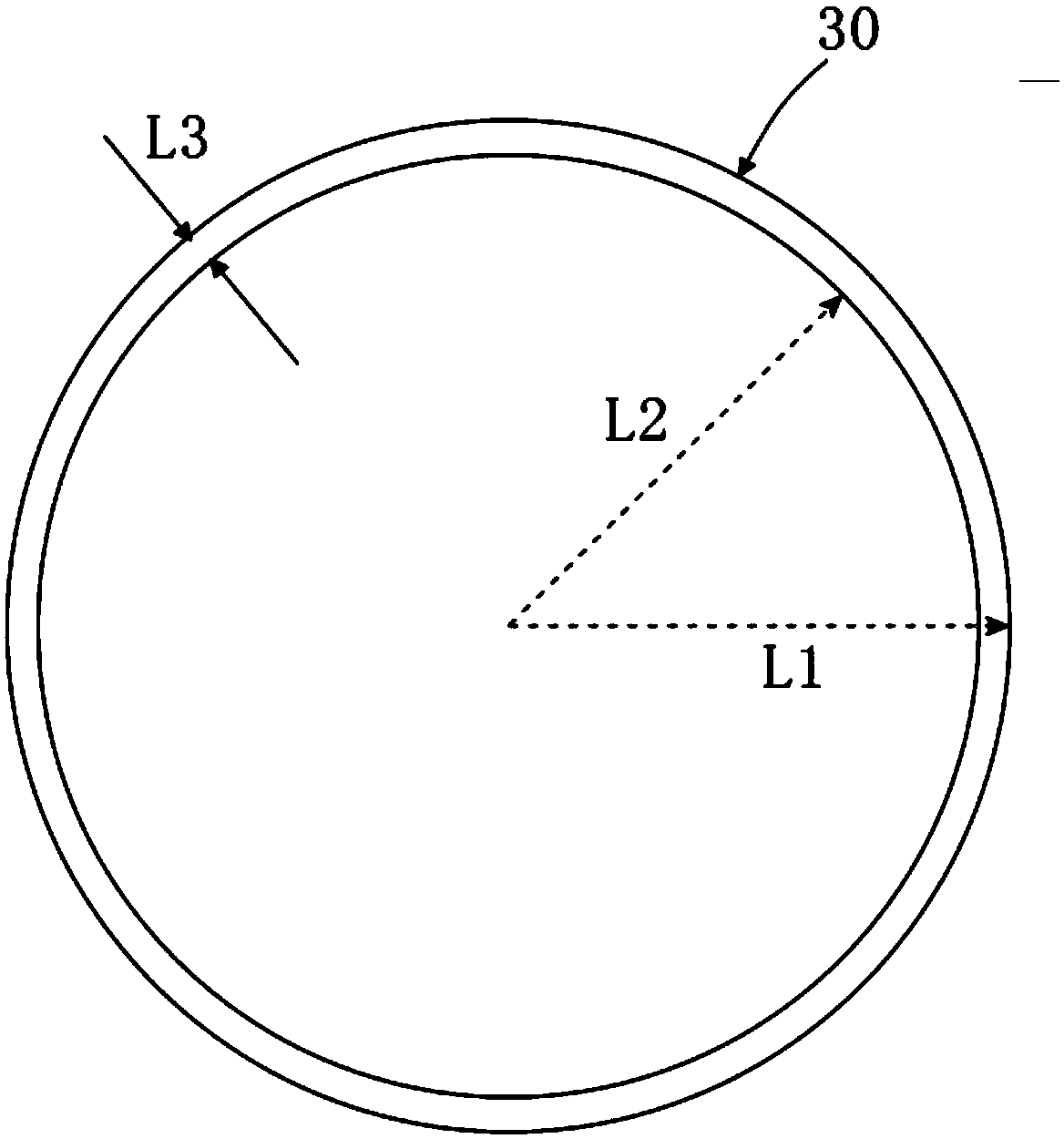
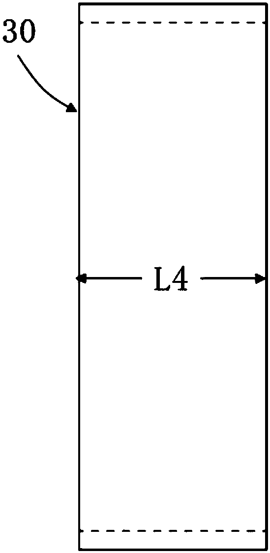
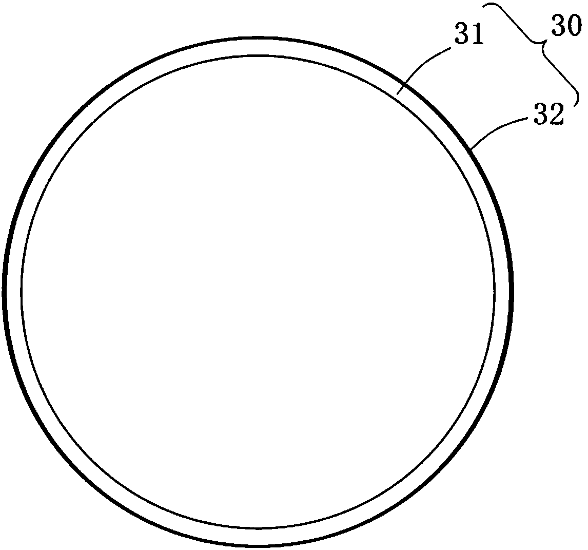
[0050] A wireless power transmission system that can be used for wireless power transmission of high-power electric vehicles at an operating frequency of 85KHz. Described system is made up of signal source 10, excitation coil 20, a pair of coils (first resonant coil 30, second resonant coil 40), receiving coil 50 and load 60 that resonant frequency is 85kHz, and wherein resonant coil is made of plexiglass plate ( Insulation dielectric plate), densely wound 22 turns of Litz wire (metal wire) and welded capacitor (lumped parameter element).

[0051] Wherein, the main preparation steps of the resonant coil include:

[0052] Use Litz wire to perform multiple dense windings on the side of the plexiglass plate, wind 22 turns, and then solder capacitors at the beginning and end of the Litz wire.

[0053] Wherein, the plexiglass plate structure of embodiment 1 is as figure 1 , fig...

Embodiment 2

[0056] Embodiment 2: the operation method of the wireless power transmission system of Embodiment 1.

[0057] A high-power and high-efficiency wireless power transmission system that can be used at an operating frequency of 85kHz such as Figure 5 As shown, let a signal at the eigenfrequency enter the exciting coil through the signal source, excite the first resonant coil, then transfer the electric energy to the second resonant coil through the near-field magnetic coupling, and finally couple the electric energy through the receiving coil as Absorbed by the load, where d1, d, and d2 represent the distance between the exciting coil and the first resonant coil, the distance between the resonant coils, and the distance between the second resonant coil and the receiving coil.

[0058] Such as Figure 6 , Figure 7 , shows the efficiency comparison diagram before and after adjusting the system to the single-mode point when the coupling distance d falls in the strong coupling reg...


PUM

PropertyMeasurementUnit
diameteraaaaaaaaaa
lengthaaaaaaaaaa
lengthaaaaaaaaaa

Abstract

The invention provides a wireless power transfer system and transfer method. The wireless power transfer system mainly consists of a signal source, an exciting coil, a pair of resonant coils with thesame resonant frequency, a receiving coil and a load; the pair of resonant coils, formed by multiple winding litz wires and loading capacitors on the side surface of an organic glass plate, are used to adjust and control the coil resonant frequency; and by virtue of single-mode point physical properties of a non-Hermitian system, the work frequency can be at the resonance frequency of the resonantcoils, for controlling the distance between the receiving coil and the adjacent resonant coil to adjust the energy transmission rate coupled out of the system, so that by changing the coupling distance of the pair of resonant coils, it is ensured that the system is in the single mode point, and the disadvantages in the prior art are overcome; and therefore, efficient wireless power transfer and single-frequency efficient wireless power transfer at the kilohertz frequency band are realized in a condition of changed coupled distances by virtue of the single single-mode point fixed frequency andthe physical properties with the minimum loss.

Description

technical field [0001] The invention relates to the technical field of wireless power transmission, in particular to a system and a transmission method for wireless power transmission using a non-radiative magnetic coupling coil. Background technique [0002] Wireless Power Transfer (WPT) is to convert electrical energy into other forms of relay energy through the transmitter, such as electromagnetic field energy, laser, microwave and mechanical waves, etc., after a certain distance is transmitted through the air, and then relayed through the receiver The energy is converted into electrical energy to realize wireless transmission of electrical energy. According to the different forms of relay energy in the process of energy transmission, it can be divided into magnetic (field) coupling, electric (field) coupling, electromagnetic radiation and mechanical wave coupling (ultrasonic coupling). Due to the large transmission power and high efficiency, the magnetic coupling wirele...

Claims


Application Information

Patent Timeline
Patent Type & Authority Applications(China)
IPC IPC(8): H02J50/12H01F38/14
CPCH01F38/14H02J50/12
Inventor 李云辉祝可嘉曾超江俊孙勇方恺陈宇光张冶文陈鸿
Owner TONGJI UNIV
Why Eureka
Try Eureka