
Hair dryer

A hair dryer and hair dryer technology, applied in clothing, hairdressing equipment, hair drying equipment, etc., can solve the problems of wind potential energy loss, poor thermal efficiency, large impeller design, etc., to reduce potential energy into heat energy and high-frequency vibration, The effect of novelty appearance

Inactive Publication Date: 2018-06-19
SHENZHEN BIANFENG ZHIQU TECH CO LTD
View PDF5 Cites 1 Cited by
  • Summary
  • Abstract
  • Description
  • Claims
  • Application Information

AI Technical Summary

Problems solved by technology

[0002] The traditional hair dryer only has one air duct, and the air in the rear is directly connected to the air in the front. Since the required air volume is collected by the impeller, the design of the impeller is relatively large, resulting in high noise, and the required air volume is passed through a wind flow, and the speed is very fast when passing through the heating wire coil, the required heating wire group is high power, in order to obtain hot air, the thermal efficiency is poor, and the energy consumption is high
[0003] Dyson proposed a brand-new hair dryer structure, by setting the motor at the handle, and setting a hollow air cylinder in the middle, and setting slits and Coanda planes on the air cylinder to discharge the air, but Dyson The air duct of the hair dryer is approximately Z-shaped, with two nearly right-angled turnings in the middle. This air duct structure will directly cause a large part of the wind potential energy to be lost, which will be converted into heat energy and high-frequency vibration.

Method used


Image

  • Hair dryer
  • Hair dryer
  • Hair dryer

Examples


Embodiment 1

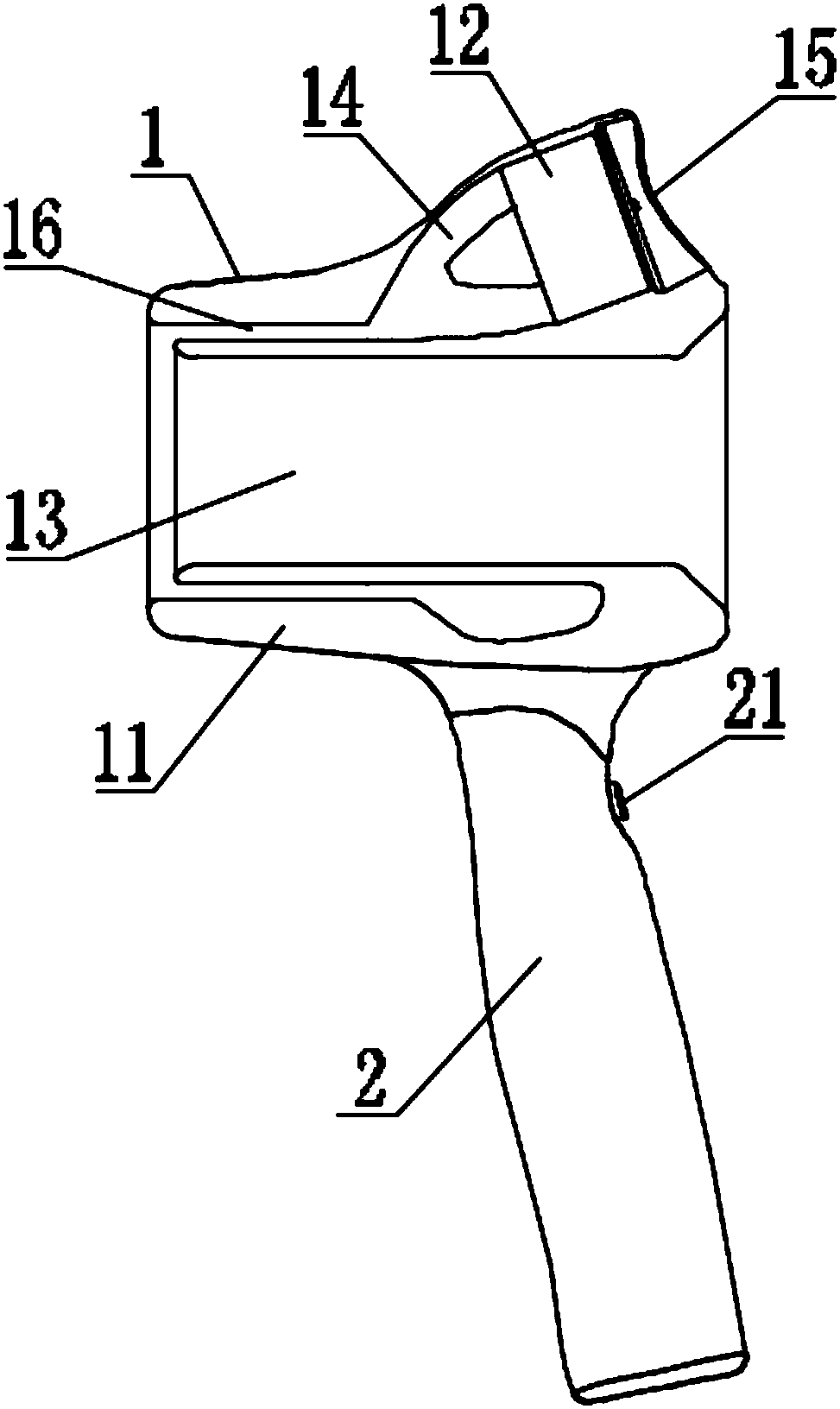
[0023] [Example 1] If figure 1 As shown, it is a structural schematic diagram of the first embodiment of the present invention. This embodiment provides a hair dryer. The hair dryer includes: an air cylinder 1 and a handle 2 connected to the air cylinder 1. The handle 2 is used for use The user holds and supports the blower 1 , the blower 1 is provided with components for generating air flow, and the handle 2 is provided with a circuit control part for controlling the blower 1 and the internal components of the blower 1 .

[0024] The blower 1 includes: a body 11 with a channel for guiding the flow of air and a motor 12 arranged in the body 11 for generating air passing through the channel. The center of the body 11 has a first air outlet channel 13. The first air outlet channel 13 runs through the body 11, forming the body 11 into an approximately hollow cylindrical structure, and the outer ring of the first air outlet channel 13 is provided with a ring that extends to the in...

Embodiment 2

[0028] [Embodiment 2] This embodiment is the second embodiment provided by the present invention. The content of this embodiment is partly the same as that of the above-mentioned embodiment, and will not be repeated here. The only difference is that the first air outlet channel The ratio of the width of 13 to the width of the second air outlet channel 16 is 10:1-2, this setting can effectively use the airflow generated by the second air outlet channel 16 to drive the airflow of the first air outlet channel 13 .

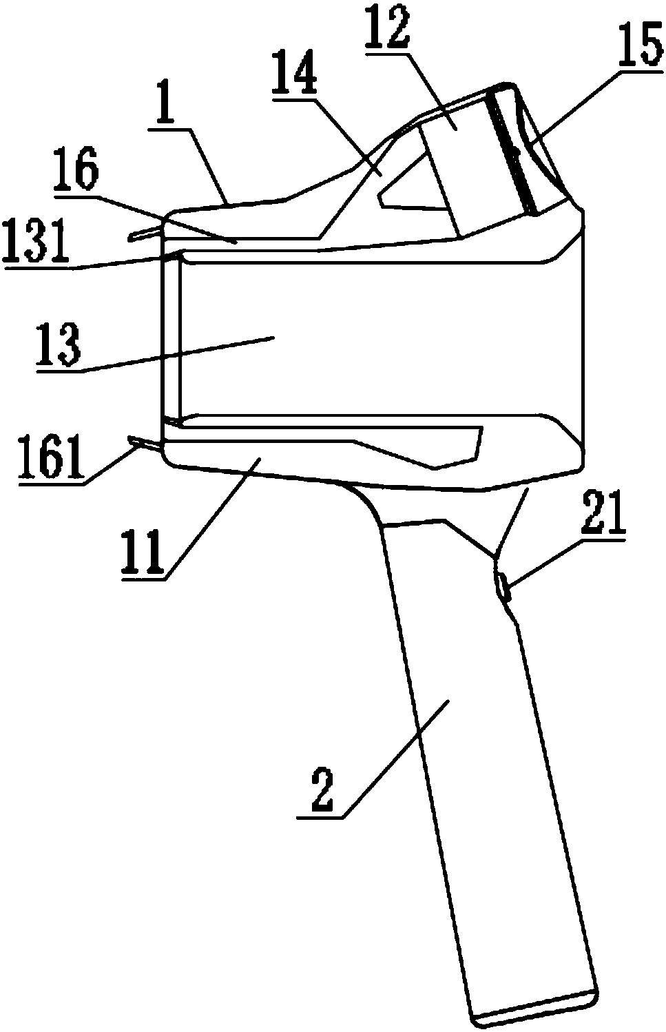
[0029] [Embodiment 3] If figure 2 As shown, it is the third embodiment provided by the present invention. The content of this embodiment is partly the same as that of the above-mentioned embodiment, and will not be repeated here. The only difference is that the air outlet of the first air outlet channel 13 is set There is an annular first guide structure 131, the angle between the first guide structure 131 and the axis of the first air outlet channel 13 is 5-15°, and...


PUM


Abstract

Provided is a hair dryer. The hair dryer comprises a wind cylinder and a handle connected to the air cylinder, and the inside of the wind cylinder is provided with a member for generating an air flow;the wind cylinder includes a body and a motor disposed in the body, a through first air outlet passage is arranged on the center of the body, the first air outlet passage is provided with a circularsecond air outlet passage extending to the inside of the body, at least one air inlet passage and the first air outlet passage are obliquely arranged, the air inlet passage communicated with the second air outlet passage is disposed inside the body, and an electric motor is disposed in the air inlet passage. The hair dryer has the advantages that the through first air outlet passage is arranged onthe center of the wind cylinder, appearance is novel, the air inlet passage and the second air outlet passage are arranged obliquely, the air flow does not lose potential energy during the flow aftermany turns, and simultaneously the potential energy is converted into heat energy and high frequency vibration.

Description

technical field [0001] The invention relates to the field of daily household appliances, in particular to a hair dryer. Background technique [0002] The traditional hair dryer only has one air duct, and the air in the rear is directly connected to the air in the front. Since the required air volume is collected by the impeller, the design of the impeller is relatively large, resulting in high noise, and the required air volume is passed through a wind Flow in the channel, and the speed is very fast when passing through the heating coil. The required heating wire group is high power to obtain hot air. The thermal efficiency is poor and the energy consumption is high. [0003] Dyson proposed a brand-new hair dryer structure, by setting the motor at the handle, and setting a hollow air cylinder in the middle, and setting slits and Coanda planes on the air cylinder to discharge the air, but Dyson The air duct of the hair dryer is approximately Z-shaped, with two nearly right-a...

Claims


Application Information

Patent Timeline
Patent Type & Authority Applications(China)
IPC IPC(8): A45D20/12
CPCA45D20/12
Inventor 翟占超金功财
Owner SHENZHEN BIANFENG ZHIQU TECH CO LTD
Learn More