

Multifunctional test tube stand used for medical examination
A multifunctional, test tube rack technology, applied in the field of medical devices, can solve the problems of test tube slippage, inconvenient use of test tube racks, single function of test tube racks, etc., and achieves the effect of improving accuracy and facilitating work.
- Summary
- Abstract
- Description
- Claims
- Application Information
AI Technical Summary
Problems solved by technology
Method used
Image

Examples
Embodiment 1
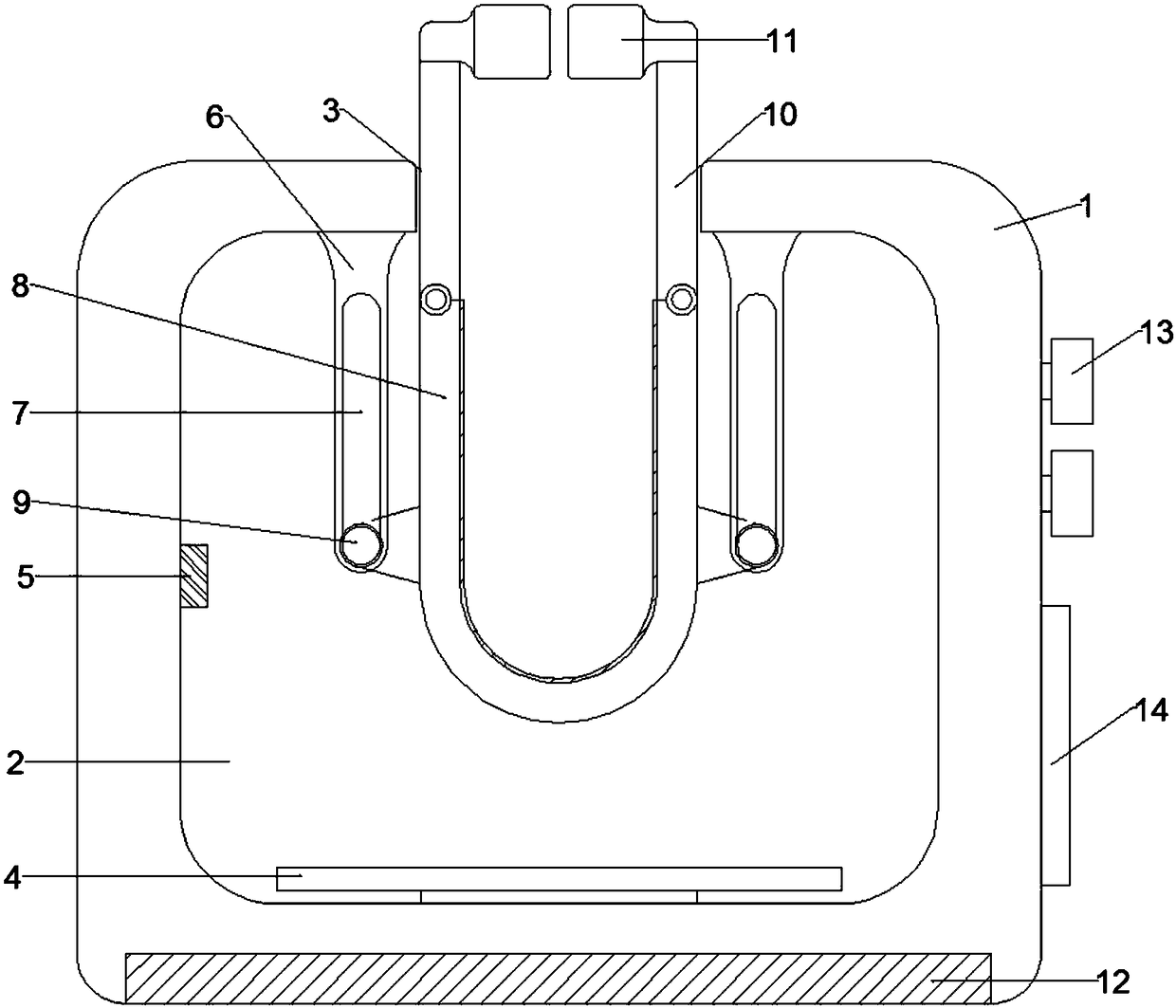
[0014] Example 1: When a test tube rack is used to fix test tubes, a multifunctional test tube rack for medical testing includes a base 1, a water tank 2 is arranged inside the base 1, and a through hole 3 that penetrates the water tank 2 is opened on the upper surface of the base 1. The inner bottom surface of the silo 2 is fixedly connected with a heating device 4, the middle of the left side wall of the water silo 2 is fixedly connected with a temperature sensing element 5, the inner top surface of the water silo 2 is located in the through hole 3, the left and right sides are fixedly connected to the supporting plate 6, the supporting plate 6 The front side is provided with a through movable groove 7, and a clamp base 8 is arranged inside the water tank 2. The clamp base 8 is fixedly connected to the sliding block 9 at the proximal end of the left and right outer side walls. The sliding block 9 is movably connected in the movable groove 7, and the clamp base 8 The top of the...
Embodiment 2
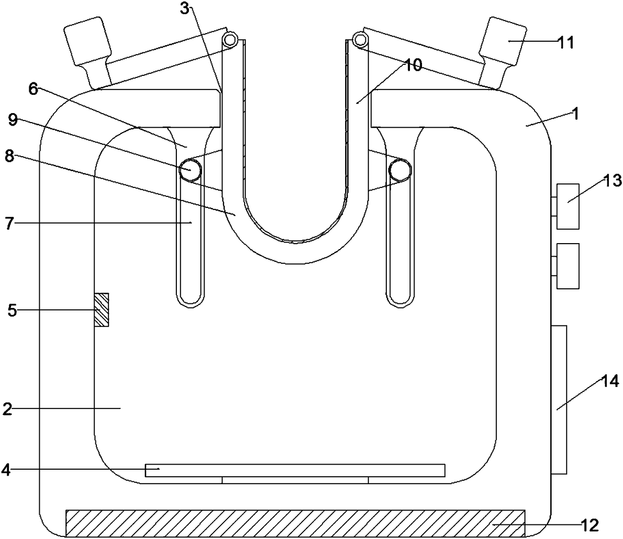
[0018] Embodiment 2: When not in use, a multifunctional test tube rack for medical examinations, comprising a base 1, characterized in that a water tank 2 is provided inside the base 1, and a through hole 3 penetrating the water tank 2 is opened on the upper surface of the base 1. The inner bottom surface of the water silo 2 is fixedly connected with a heating device 4, the middle of the left side wall of the water silo 2 is fixedly connected with a temperature sensing element 5, the inner top surface of the water silo 2 is located in the through hole 3, and the left and right sides are fixedly connected to the supporting plate 6, the supporting plate 6 The front side is provided with a through movable groove 7, and the water tank 2 is provided with a clamp base 8. The clamp base 8 is fixedly connected to the sliding block 9 at the proximal end of the left and right outer side walls. The sliding block 9 is movably connected in the movable groove 7, and the clamp base 8 is hinged...
PUM
 Abstract
Description
Claims
Application Information