Laminating device of die cutting machine

A technology of laminating device and die-cutting machine, which is applied in metal processing and other directions, can solve problems such as defective products, film stretching, deformation and bending of main materials, and achieve the effects of improving production efficiency, reducing stretching, and avoiding bending deformation

Active Publication Date: 2018-06-19
SHENZHEN REBORN PRECISION MACHINERY CO LTD
View PDF7 Cites 0 Cited by
  • Summary
  • Abstract
  • Description
  • Claims
  • Application Information

AI Technical Summary

Problems solved by technology

[0003] However, since the paper feeding mode of the die-cutting machine is one stop and one stop, it will have an impact on the material. When the film lamination process is required, because the material thickness of the film itself is very thin, it is easy to cause the film to be stretched. The shrinkage of the back film will deform and bend the main material, resulting in the occurrence of defective products

Method used


Image

  • Laminating device of die cutting machine
  • Laminating device of die cutting machine
  • Laminating device of die cutting machine

Examples


Embodiment Construction

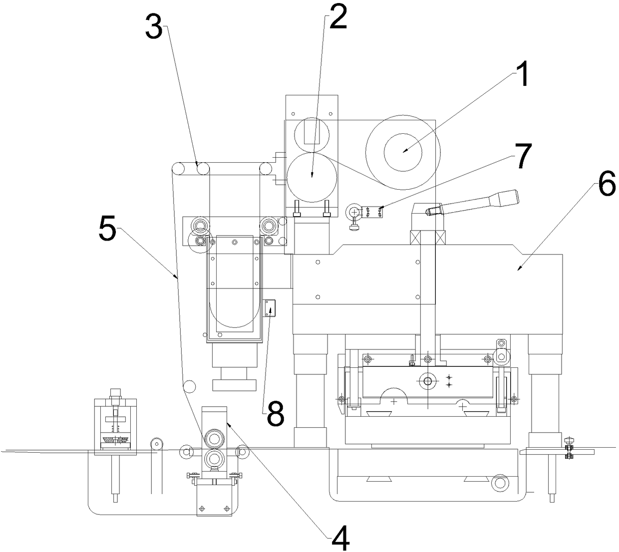
[0035] see figure 1 , the present invention relates to a film coating device of a die-cutting machine, comprising a film releasing shaft device 1, a film pulling device 2, a laminating device 4, and a film guide roller device 3, the film releasing shaft device 1, a film pulling device 2. The film guide roller device 3 is arranged on the upper end of the die-cutting machine 6 in sequence, and the bonding device 4 is arranged below the film guide roller device 3; the film coating material 5 is wound on the film release shaft device 1, and the film The material 5 passes through the film pulling device 2, the film guide roller device 3, and the laminating device 4 in sequence, and then is pasted on the main material, and is pressed on the main material by the die-cutting machine 6;

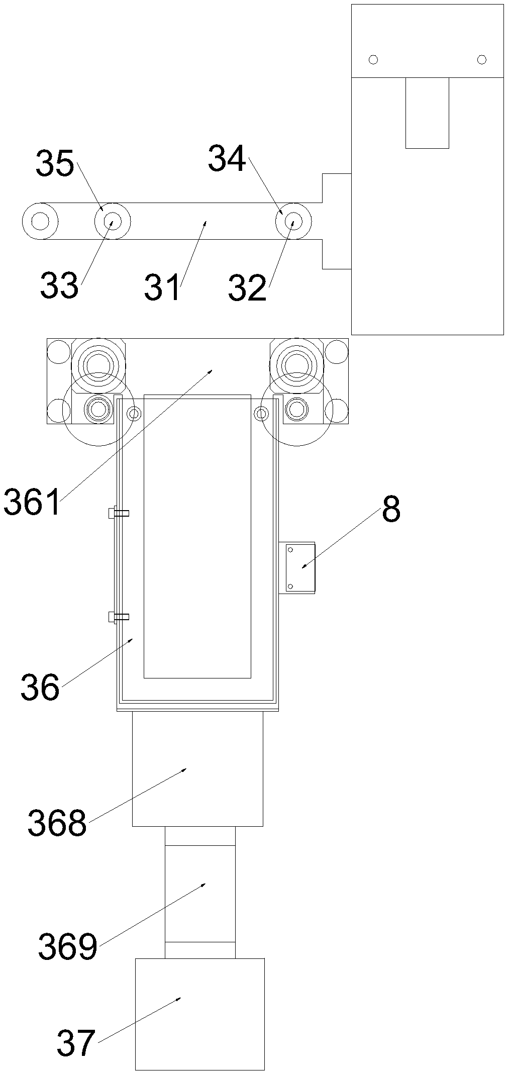
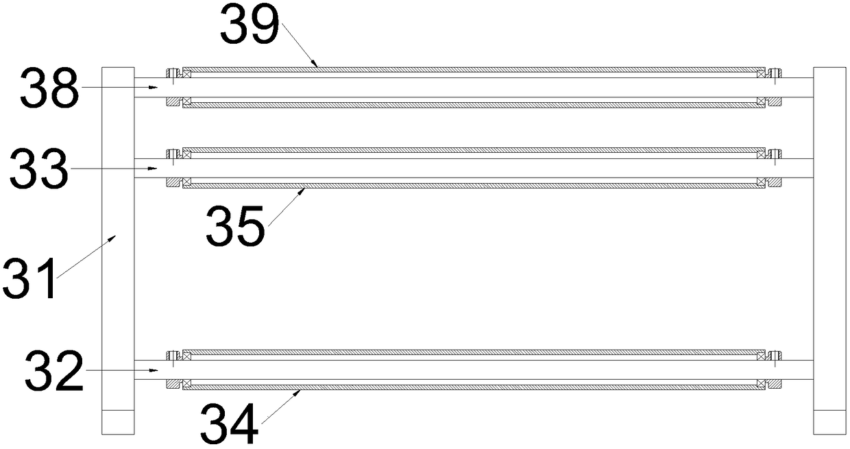
[0036] see Figure 2-3 , the film guide roller device 3 includes a film guide roller upper side plate 31, a first film guide roller shaft 32, a second film guide roller shaft 33, a first film guide r...


PUM


Abstract

The invention discloses a laminating device of a die cutting machine. A film guiding roller device comprises film guiding roller upper side plates, a first film guiding roller shaft, a second film guiding roller shaft, a first film guiding roller, a second film guiding roller, a tension air bellow and a draught fan. The film guiding roller upper side plates are oppositely arranged. The first filmguiding roller shaft and the second film guiding roller shaft are sequentially arranged between the film guiding roller upper side plates. The two ends of the first film guiding roller shaft and the two ends of the second film guiding roller shaft are connected with the film guiding roller upper side plates through bolts. The first film guiding roller and the second film guiding roller are correspondingly in cup joint to the first film guiding roller shaft and the second film guiding roller shaft through bearings. An interval is reserved between the first film guiding roller and the second film guiding roller. The tension air bellow is arranged under the interval between the first film guiding roller and the second film guiding roller. The draught fan is arranged at the lower end of the tension air bellow. The wind direction of the draught fan acts on the interval between the first film guiding roller and the second film guiding roller. The draught fan and the tension air bellow applydownward pressure to a laminating material, constant tension of the laminating material is guaranteed, and main material bending and deforming after laminating and combining are avoided.

Description

technical field [0001] The invention relates to the field of die-cutting machines, in particular to a film covering device of a die-cutting machine. Background technique [0002] The die-cutting machine is mainly the main equipment for printing and paper packaging. The working principle of the die-cutting machine is to use the template carved by steel knife, metal mold, steel wire or steel plate, and apply a certain pressure through the embossing plate to convert the printed matter or cardboard Cut into certain shapes. The main parts of the die-cutting machine are the die-cutting platen and the press-cutting mechanism. Among them, the working principle of the die-cutting device is: the die-cutting work is completed under the action of pressure. Simply speaking, the die-cutting pressure is controlled by the movable platform. The press fit with the upper fixed platform takes place. [0003] However, since the paper feeding mode of the die-cutting machine is one stop and one ...

Claims


Application Information

Patent Timeline
Patent Type & Authority Applications(China)
IPC IPC(8): B26F1/38B26D7/27B29C63/00B29C31/04
CPCB26D7/27B26F1/38B29C31/04B29C63/0004B29C63/0056Y02E60/10
Inventor 邹平
Owner SHENZHEN REBORN PRECISION MACHINERY CO LTD
Why Eureka
Try Eureka