Surface nanocrystallization method capable of accelerating vacuum carburizing rate

A vacuum carburizing and nanotechnology, which is applied in the direction of coating, metal material coating process, solid diffusion coating, etc., can solve the problems of long carburizing cycle, uneven carburizing layer structure, high energy consumption, etc., and achieve carburizing The effect of rate increase, accelerated carburizing rate, and uniform carburizing layer structure

Inactive Publication Date: 2018-06-19
HARBIN ENG UNIV
View PDF5 Cites 8 Cited by
  • Summary
  • Abstract
  • Description
  • Claims
  • Application Information

AI Technical Summary

Problems solved by technology

[0006] The purpose of the present invention is to solve the problems of uneven carburizing structure, long carburizing cycle and high energy consumption in the existing vacuum carburizing technology, and provide a vacuum carburizing process for accelerating carburizing rate and improving carburizing structure. A composite surface strengthening method that uses supersonic particle bombardment technology to form a nano-modified layer on the surface of the substrate before vacuum carburizing

Method used


Image

  • Surface nanocrystallization method capable of accelerating vacuum carburizing rate
  • Surface nanocrystallization method capable of accelerating vacuum carburizing rate
  • Surface nanocrystallization method capable of accelerating vacuum carburizing rate

Examples


specific Embodiment approach 1

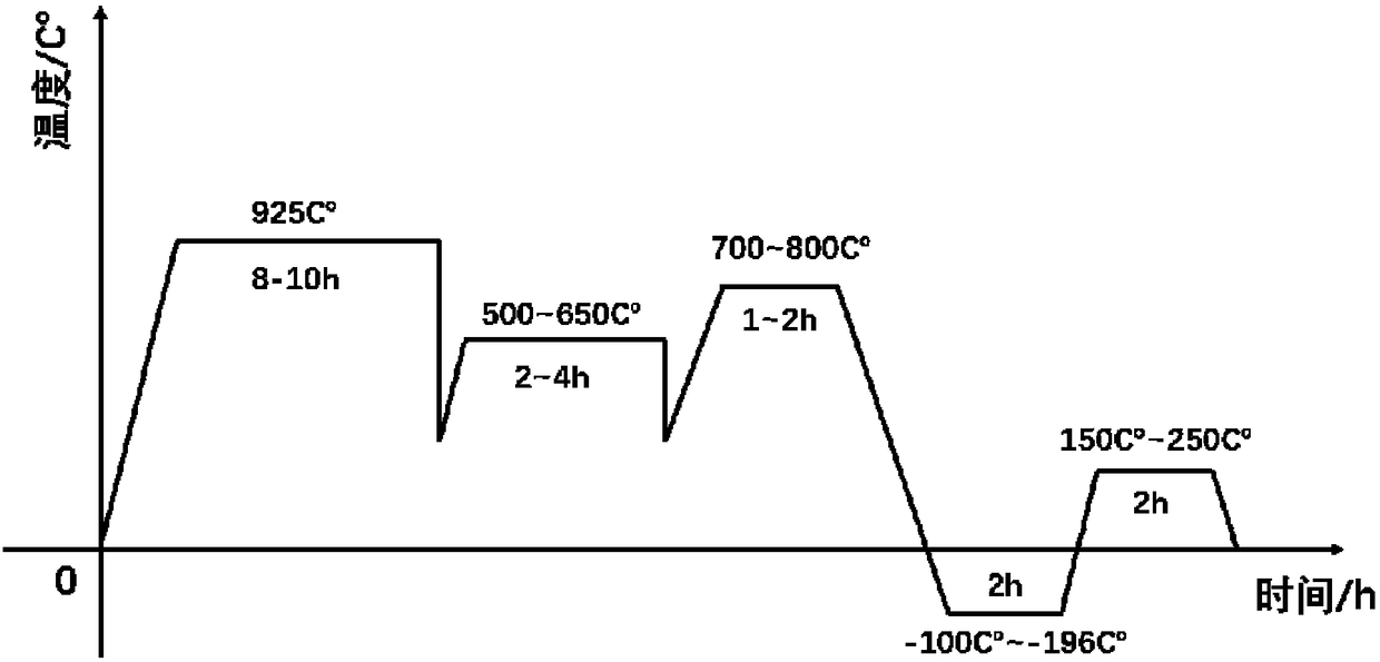
[0019] Specific Embodiment 1: In this embodiment, the surface nanometerization method for accelerating the vacuum carburizing rate is implemented according to the following steps:

[0020] 1. Cut the matrix material into shape, clean the surface of the matrix material with acetone, then polish the surface of the matrix material with sandpaper and polish it, then perform ultrasonic cleaning with absolute ethanol, and obtain the cleaned matrix material after drying;

[0021] 2. Clamp the cleaned matrix material into the fixture to obtain the fixture with the matrix material clamped therein;

[0022] 3. Place the clamp with the matrix material in the supersonic particle bombardment device for surface nano-treatment, move the spray gun during the surface nano-treatment process to obtain uniform surface nano-treatment at different positions on the surface of the substrate per unit time, Obtain a matrix material modified by surface nanometerization;

[0023] 4. Put the surface nano...

specific Embodiment approach 2

[0026] Embodiment 2: The difference between this embodiment and Embodiment 1 is that the base material in step 1 is 18Cr2Ni4WA, 20Cr2Ni4, 12Cr2Ni4 or 20CrMoMn.

specific Embodiment approach 3

[0027] Specific embodiment three: the difference between this embodiment and specific embodiment one or two is that in step one, use 60#, 240#, 600#, 800#, 1000#, 2000#, 3000# sandpaper to polish the surface of the base material.


PUM


Abstract

The invention discloses a surface nanocrystallization method capable of accelerating vacuum carburizing rate, belongs to the field of heat treatment and surface engineering, aims to solve the problemsof inhomogeneous infiltration layer and long carburizing cycle in the prior art of the vacuum carburizing. The surface nanocrystallization method comprises the steps that firstly, matrix material acetone is shined and polished after the matrix material acetone is cleaned; secondly, the matrix material is packed into a fixture; thirdly, the fixture packed with the matrix material is placed in a supersonic fine particle bombardment device for the surface nanocrystallization treatment; fourthly, the matrix material after the surface nanocrystallization modification is subject to the vacuum carburizing treatment by the cyclic pulse mode; and fifthly, the matrix material is subjected to the heat treatment. According to the surface nanocrystallization method capable of accelerating the vacuum carburizing rate, a sample which is subject to the vacuum carburizing treatment after surface nanocrystallization osmosis treatment is reduced in the carbide grade of the infiltration layer, is finer and dispersed, and isobviously improved in the carburizing speed; and the vacuum carburizing speed by the surface nanocrystallization osmosis treatment is increased by about 24% compared with ordinaryvacuum carburizing speed.

Description

technical field [0001] The invention belongs to the field of heat treatment and surface engineering, and in particular relates to a method for preparing a nano-modified layer on the surface of a material by using surface nano-technology, accelerating the vacuum carburizing rate and improving the quality of the carburizing layer. Background technique [0002] Vacuum carburizing technology is a carburizing heat treatment technology carried out in a vacuum environment. It ensures high hardness on the surface and toughness at the core. Compared with traditional atmosphere carburizing, it can effectively prevent surface carbon black and intragranular Oxidation, can be carburized at a higher temperature to shorten the carburizing time, more economical and environmentally friendly. However, there are still problems such as high carburizing temperature, long carburizing cycle, and large energy consumption. The process is optimized and corresponding auxiliary means are added to study...

Claims


Application Information

Patent Timeline
Patent Type & Authority Applications(China)
IPC IPC(8): C23C8/22C21D7/06C23C8/02C23C8/80C21D1/18C21D6/04
CPCC23C8/22C21D1/18C21D6/04C21D7/06C23C8/02C23C8/80
Inventor 金国赵鑫崔秀芳董美伶冯相如卢冰文宋圣强
Owner HARBIN ENG UNIV
Why Eureka
Try Eureka