
Relay lens and lighting system

A lighting system and lens technology, applied in the field of lighting, can solve the problems of high sag height of the relay lens and large receiving angle of the relay lens, and achieve the effect of reducing the sag height and the total length.

Active Publication Date: 2018-06-19
JOURNEY TECH LTD
View PDF8 Cites 0 Cited by
  • Summary
  • Abstract
  • Description
  • Claims
  • Application Information

AI Technical Summary

Problems solved by technology

Generally, in order to make better use of the light emitted by the light source, the acceptance angle of the relay lens needs to be as large as possible, which will result in a larger sagittal height of the relay lens

Method used


Image

  • Relay lens and lighting system
  • Relay lens and lighting system
  • Relay lens and lighting system

Examples


Embodiment Construction

[0033] The following description and drawings illustrate specific embodiments of the invention sufficiently to enable those skilled in the art to practice them. The examples merely represent possible variations. Individual components and functions are optional unless explicitly required, and the order of operations may vary. Portions and features of some embodiments may be included in or substituted for those of other embodiments. The scope of embodiments of the present invention includes the full scope of the claims, and all available equivalents of the claims. Herein, various embodiments may be referred to individually or collectively by the term "invention", which is for convenience only and is not intended to automatically limit the scope of this application if in fact more than one invention is disclosed. A single invention or inventive concept. Herein, relational terms such as first and second etc. are used only to distinguish one entity or operation from another with...


PUM


Abstract

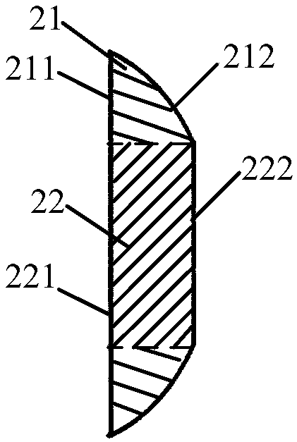
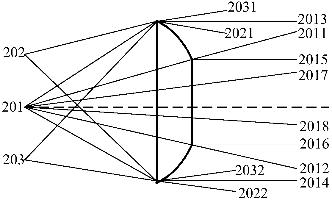
The invention discloses a relay lens and a lighting system. The relay lens comprises a first part and a second part. The first incident plane of the first part is a plane perpendicular to the light path, and a first emitting face of the first part is a convex ball face. The second part is located at the center position of the first part, a second incident plane of the second part is a plane perpendicular to the light path, and the curvature of a second emitting face of the second part is smaller than the curvature of the first emitting face. Due to the fact that no strict requirements for whether the lighting light rays at the center position are collimated into parallel light rays or not exist, when the curvature of the second emitting face of the second part located at the center position of the first part is smaller than the curvature of the first emitting face of the first part, the rise of the relay lens can be reduced on the premise that the lighting effect is not influenced, andaccordingly, the total length of the relay lens is reduced.

Description

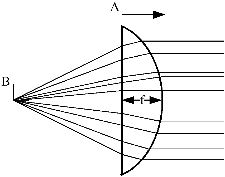
technical field [0001] The invention relates to the lighting field, in particular to a relay lens and a lighting system. Background technique [0002] The miniaturization of optical path structure is the development trend of optical instruments, especially in the field of lighting of wearable devices, the demand for miniaturized optical instruments is even stronger. However, miniaturized optical paths generally require novel optical components, such as aspheric surfaces, Fresnel lenses, and binary optical lenses. Compared with spherical lens elements, the processing technology of these lens elements is very difficult, which is reflected in the fact that the required processing machine tools and testing equipment are very complicated, which will inevitably increase the cost and processing cycle of such elements. [0003] figure 1 is a schematic diagram of a relay lens in a lighting system of a prior art wearable device. The relay lens is a spherical lens, the direction A i...

Claims


Application Information

Patent Timeline
IPC IPC(8): F21S2/00F21V5/00F21V5/04G02B13/00
CPCF21S2/00F21V5/004F21V5/04G02B13/0095
Inventor 刘健鹏郑昱
Owner JOURNEY TECH LTD
Learn More