
Probe structure, test device and test method

A test device and probe technology, applied in the field of testing, can solve the problems of the probe moving out of the via hole, long time, experiment failure, etc.

Active Publication Date: 2018-06-19
BOE TECH GRP CO LTD +1
View PDF6 Cites 2 Cited by
  • Summary
  • Abstract
  • Description
  • Claims
  • Application Information

AI Technical Summary

Problems solved by technology

[0004] At present, when testing the transfer characteristics of thin-film transistors (TFTs) in COA products, the test probes of the drain (Drain) usually need to be pierced on the via holes, and due to the small size of the via holes, the thermal expansion of the TFT during the transfer characteristic test will cause problems. Make the probe move out of the via, making the experiment fail
However, the transfer characteristic test takes a long time. If the test failure cannot be detected in time, time will be wasted and the test efficiency will be low.

Method used


Image

  • Probe structure, test device and test method
  • Probe structure, test device and test method
  • Probe structure, test device and test method

Examples


Embodiment Construction

[0033] In order to make the object, technical solution and advantages of the present invention clearer, the present invention will be described in further detail below in conjunction with specific embodiments and with reference to the accompanying drawings.

[0034] It should be noted that all expressions using "first" and "second" in the embodiments of the present invention are to distinguish two entities with the same name but different parameters or parameters that are not the same, see "first" and "second" It is only for the convenience of expression, and should not be construed as a limitation on the embodiments of the present invention, which will not be described one by one in the subsequent embodiments.

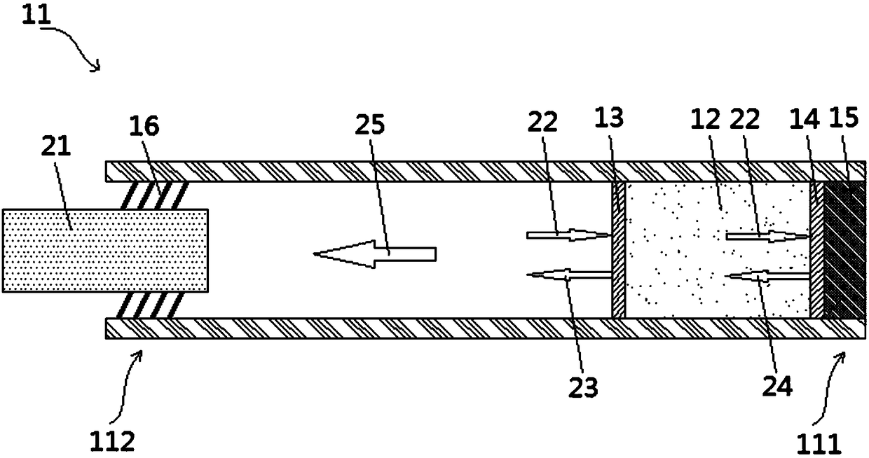
[0035] The first aspect of the embodiments of the present invention provides an embodiment of a probe structure, which can better complete TFT testing. Such as figure 1 Shown is a structural schematic diagram of an embodiment of the probe structure provided by the pr...


PUM


Abstract

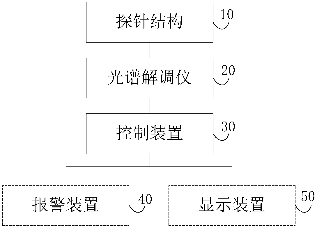
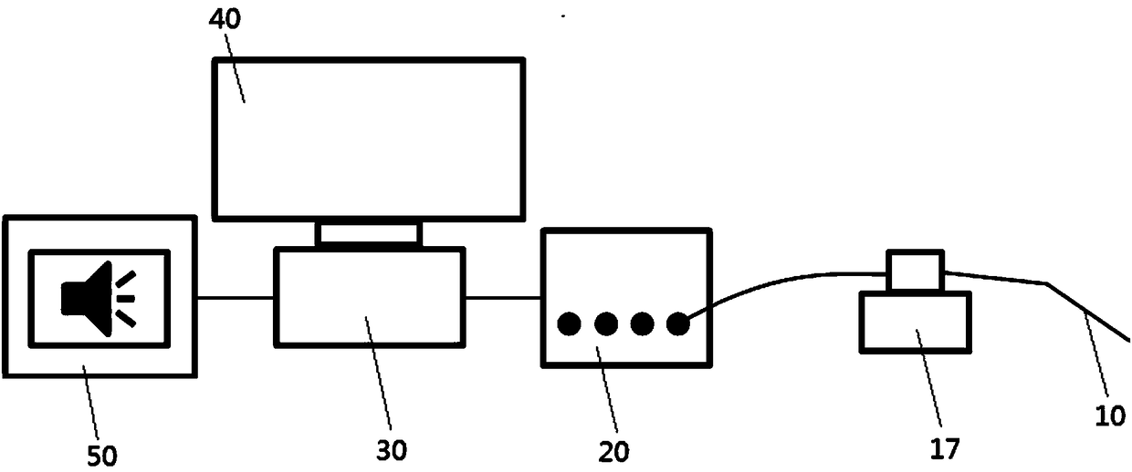
The invention discloses a probe structure which comprises a hollow probe head and a filling material. The filling material is arranged inside the first end of the hollow probe head. The first end contacts an object to be tested. At least one of the thermal expansion coefficient, thermo-optic coefficient and elasto-optic coefficient of the filling material is greater than a preset coefficient threshold. The second end of the hollow probe head is connected with a light transmitting optical fiber of a spectrum demodulator. The invention further discloses a test device and a test method. Accordingto the probe structure, the test device and test method, TFT testing can be well carried out.

Description

technical field [0001] The invention relates to the technical field of testing, in particular to a probe structure, a testing device and a testing method. Background technique [0002] COA technology, Color filter on array, is a technology that fabricates a color filter layer and a black matrix on an array substrate. This technology can effectively eliminate the problems of reduced aperture ratio and light leakage of the display device caused by the deviation between the color filter substrate and the array substrate when the color filter layer and the black matrix are fabricated on the color filter substrate. [0003] However, the inventor found that the prior art has the following problems when implementing the present invention: [0004] At present, when testing the transfer characteristics of thin-film transistors (TFTs) in COA products, the test probes of the drain (Drain) usually need to be pierced on the via holes, and due to the small size of the via holes, the ther...

Claims


Application Information

Patent Timeline
IPC IPC(8): G01K11/32G01K1/14G01K1/02
CPCG01K1/14G01K11/32
Inventor 付剑波吴海龙周焱毛大龙梁鹏冉敏许卓但艺朱海鹏
Owner BOE TECH GRP CO LTD
Learn More