Food waste treating device

A food waste treatment and grinding technology, which is applied in grain treatment, indoor sanitary plumbing installations, water supply installations, etc., can solve the problems of increasing working time, reducing machine efficiency, and small centrifugal force, so as to increase the radius of rotation and improve work efficiency. Efficiency, friction reduction effect

Inactive Publication Date: 2018-06-22
SKYBEST ELECTRIC APPLIANCE SUZHOU CO LTD
View PDF0 Cites 2 Cited by
  • Summary
  • Abstract
  • Description
  • Claims
  • Application Information

AI Technical Summary

Problems solved by technology

[0003] The cutting and crushing structure of the food grinder on the market is mostly a planar structure. This structure completely uses the centrifugal force after rotation to throw the food away. In the middle of the machine cutter head, due to the extremely small radius of rotation, the centrifugal force will be very small, and the friction force will be large, which will eventually make it difficult for the food to be thrown around, which will increase the working time and reduce the efficiency of the machine.
In addition, in real life, if we pour some food waste into the food grinder first, since the machine is not running at this time, the food will accumulate in the middle of the cutterhead structure, which will reduce the amount of food waste poured in and make the user operate frequently complex

Method used


Image

  • Food waste treating device
  • Food waste treating device
  • Food waste treating device

Examples


Embodiment Construction

[0057] The present invention will be described in detail below with reference to the embodiments shown in the accompanying drawings. However, these embodiments do not limit the present invention, and structural or functional changes made by those skilled in the art according to these embodiments are included in the protection scope of the present invention.

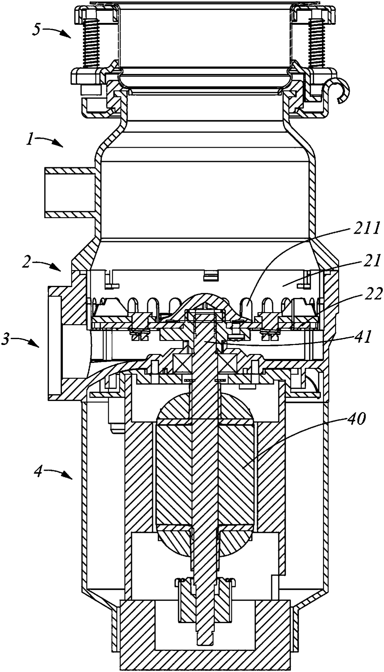
[0058] refer to figure 1 As shown, it is the first preferred embodiment of the food waste disposer of the present invention. The food waste disposer includes a food waste conveying part 1, a grinding and discharging part and a motor part 4 arranged from top to bottom, wherein the grinding and discharging part includes The grinding part 2 and the discharge part 3, the food waste conveying part 1 is used to transport the food waste to the grinding part 2, and discharge from the discharge part 3 after being ground by the grinding part 2. The motor section 4 includes a motor 40, which is preferably an electric motor. The gr...


PUM


Abstract

The invention provides a food waste treating device. The device comprises a grinding crushing part and a motor part which are arranged from top to bottom, wherein the grinding crushing part comprisesa grinding crushing mechanism; the grinding crushing mechanism comprises a static grinding crushing ring and a rotary crushing assembly; the rotary crushing assembly comprises a grinding plate which is provided with one or a plurality of protruding blocks; a motor of the motor part is capable of driving the grinding plate to rotate through a driving shaft; a protruded part with a crest shaped section is arranged in the middle part of the grinding plate. According to the food waste treating device, the protruded part is arranged in the middle part of the grinding disc, and the section of the protruded part is of a crest structure, so that food wastes entering a grinding chamber are difficultly accumulated in the middle of the grinding plate, and moreover, the frictional force relative to the grinding plate can be reduced, the rotating radius can be increased, the centrifugal force can be improved, and as a result, foods are more easily thrown to the surrounding to be cut and ground, andthe working efficiency is improved.

Description

technical field [0001] The invention relates to a food waste disposer. Background technique [0002] The existing food waste disposer is arranged under the sink and installed at the drain of the sink, which usually includes a food conveying part, a motor part and a grinding part. The grinding part is arranged between the food conveying part and the motor part. The food conveying part conveys the food waste to the grinding part. The grinding part receives food waste and grinds it, and the ground food waste is discharged to the tailpipe through the discharge outlet. [0003] The cutting and crushing structure of the food grinder on the market is mostly a planar structure. This structure completely uses the centrifugal force after rotation to throw the food away. In the middle of the machine cutter head, due to the extremely small radius of rotation, the centrifugal force will be very small, and the friction force will be large, which will eventually make it difficult for th...

Claims


Application Information

Patent Timeline
Patent Type & Authority Applications(China)
IPC IPC(8): B02C18/12B02C18/18B02C18/22B02C18/24B02C18/16E03C1/266
CPCB02C18/12B02C18/0092B02C18/16B02C18/18B02C18/22B02C18/24B02C2201/06E03C1/2665
Inventor 孔钊郭宁朱光跃
Owner SKYBEST ELECTRIC APPLIANCE SUZHOU CO LTD
Why Eureka
Try Eureka