
Full-automatic test tube dry ice cleaning machine

A dry ice cleaning, fully automatic technology, applied in the direction of cleaning hollow objects, cleaning methods and utensils, chemical instruments and methods, etc., can solve the problems of difficult cleaning of attachments, hidden dangers of operator safety, fragile and other problems

Inactive Publication Date: 2018-06-22
马翔宇 +2
View PDF0 Cites 4 Cited by
  • Summary
  • Abstract
  • Description
  • Claims
  • Application Information

AI Technical Summary

Problems solved by technology

[0002] At present, there are two main cleaning methods for various medical test tubes: one is to use manual cleaning, the existing problems and shortcomings are as follows: after use, there are residues on the inner wall of the test tube made of glass, and it is very difficult to clean the attachments. Cleaning the test tube is time-consuming and laborious, and a certain amount of corrosive agent remains after manual cleaning, which is fragile during the operation and poses a safety hazard to the operator
Another way is to use ultrasonic waves for cleaning. The existing problems and disadvantages are as follows: cleaning requires the use of distilled water, which is costly and consumes a lot of energy; the number of test tubes put in each time is small, the cleaning efficiency is low, and manual work is required before and after cleaning. loading and unloading

Method used


Image

  • Full-automatic test tube dry ice cleaning machine
  • Full-automatic test tube dry ice cleaning machine
  • Full-automatic test tube dry ice cleaning machine

Examples


Embodiment Construction

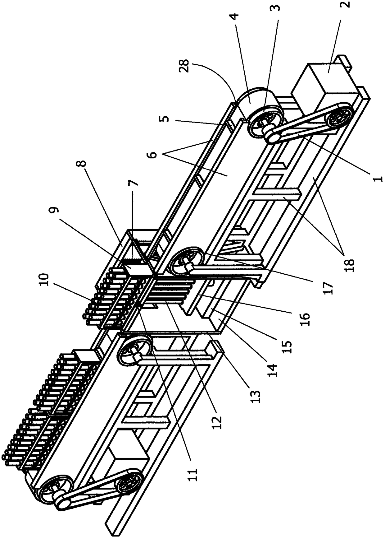
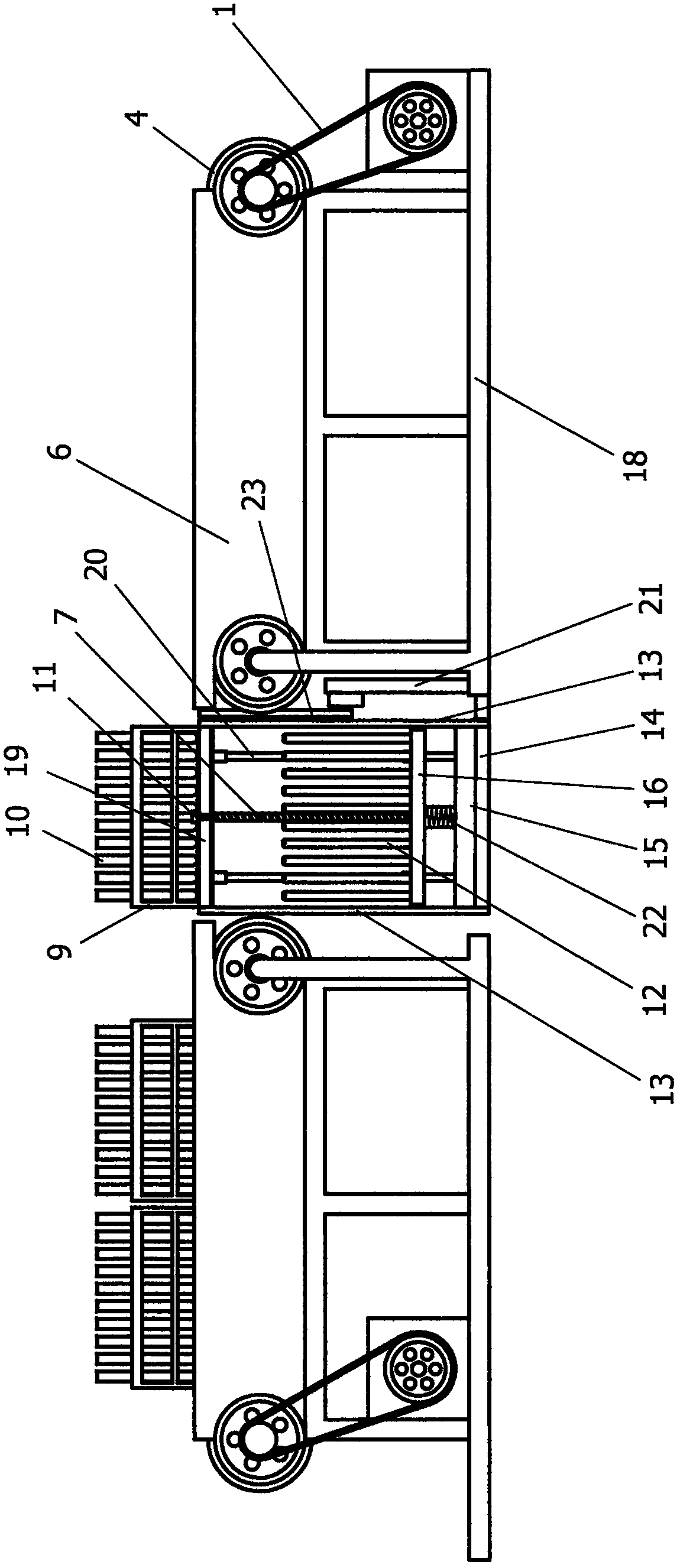
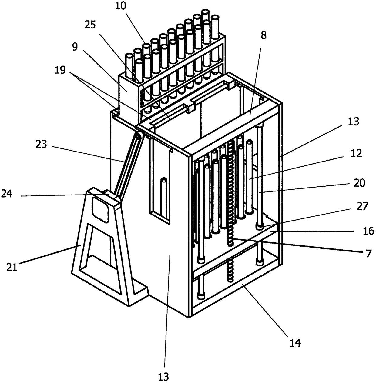
[0016] Such as figure 1 , 2 , 3 shows: the automatic test tube dry ice blasting machine of the present invention includes a dry ice blasting part located in the middle and symmetrically arranged conveying parts located on both sides of the dry ice blasting part.

[0017] The conveying parts on the left and right are identical in structure. Including the conveying frame 18, the driving roller 3 and the driven roller 17 are respectively installed on the two ends of the upper part of the conveying frame 18 through shafts and bearings. In the conveying motor 2 on the conveying frame 18, there is a conveying transmission pair 1 between the output shaft of the conveying motor 2 and the shaft end of the drive roller 3, and the conveying transmission pair 1 can be a chain mechanism or a belt mechanism.

[0018] A belt 4 is wound around the driving roller 3 and the driven roller 17, and baffles 5 are arranged at intervals on the belt 4, and the baffles 5 prevent the conveyed items on...


PUM


Abstract

Disclosed is a full-automatic test tube dry ice cleaning machine. The full-automatic test tube dry ice cleaning machine comprises a dry ice cleaning part and a conveying part; and the conveying part consists of a driving roller, a driven roller and a conveyor belt on the rack; the dry ice cleaning part comprises a frame, the upper end of the frame is connected with an overturning drive mechanism and overturning frames, and a box frame is matched with the overturning frames and the conveyor belt. The overturning frames and the box frame have a gear rack drive pair. The lower portion of the frame is provided with a dry ice machine, a lifting box is arranged above the dry ice machine, the inner cavity of the lifting box is connected with an ice jetting opening of the dry ice machine through atelescopic pipe, and the lifting box is connected with a lifting and driving mechanism. A plurality of vertically-arranged ice jetting pipes are connected to the lifting box, the inner cavities of the ice jetting pipes communicate with the inner cavity of the lifting box, and the upper ends of the ice jetting pipes are provided with the ice jetting opening. When the overturning frames rotate downwards, end openings of test tubes inserted into the box frame can be exactly corresponding to the ice jetting pipes. The full-automatic test tube dry ice cleaning machine has the advantages of being capable of being cleaned in batch, high in automation degree, time-saving and labor-saving, thorough in cleaning, low in cost, and low in energy consumption.

Description

technical field [0001] The invention relates to a cleaning device, in particular to a medical automatic test tube dry ice cleaning machine. Background technique [0002] At present, there are two main cleaning methods for various medical test tubes: one is to use manual cleaning, the existing problems and shortcomings are as follows: after use, there are residues on the inner wall of the test tube made of glass, and it is very difficult to clean the attachments. Cleaning the test tube is time-consuming and laborious, and a certain amount of corrosive agent remains after manual cleaning, which is fragile during the operation and poses a safety hazard to the operator. Another way is to use ultrasonic waves for cleaning. The existing problems and disadvantages are as follows: cleaning requires the use of distilled water, which is costly and consumes a lot of energy; the number of test tubes put in each time is small, the cleaning efficiency is low, and manual work is required b...

Claims


Application Information

Patent Timeline
IPC IPC(8): B08B9/20B08B9/44
CPCB08B9/20B08B9/44
Inventor 马一鸣马翔宇张美琪侯睿刘明泽苏广赫
Owner 马翔宇
Features
  • Generate Ideas
  • Intellectual Property
  • Life Sciences
  • Materials
  • Tech Scout
  • Unparalleled Data Quality
  • Higher Quality Content
  • 60% Fewer Hallucinations
Learn More