
Stainless steel jacket continuous stamping device

A technology of stamping device and stainless steel sleeve, applied in the field of stamping device, can solve the problems of affecting the service life, lack of stainless steel sleeve protective components, lack of cleaning components on the operating table, etc., and achieves strong adaptability, improved processing and production effect, and good cleaning effect. Effect

Inactive Publication Date: 2018-06-22
JIANGSU TAI TONG NEW MATERIAL CO LTD
View PDF0 Cites 2 Cited by
  • Summary
  • Abstract
  • Description
  • Claims
  • Application Information

AI Technical Summary

Problems solved by technology

[0003] Existing stamping devices for stainless steel sleeves have relatively simple functions, and the actual use effect needs to be improved. For example, the stamping structure is relatively fixed, and the adjustment effect is poor. The stamping device lacks the stainless steel sleeve and its own protective components, which is likely to cause impact damage and affect its service life. In addition, there is no cleaning component for the operation table after stamping, which is not conducive to subsequent processing and production.

Method used


Image

  • Stainless steel jacket continuous stamping device
  • Stainless steel jacket continuous stamping device
  • Stainless steel jacket continuous stamping device

Examples


Embodiment Construction

[0019] In order to make the technical means, creative features, goals and effects achieved by the present invention easy to understand, the present invention will be further described below in conjunction with specific embodiments.

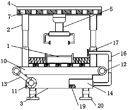
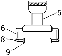
[0020] Such as Figure 1-3 As shown, a stainless steel sleeve continuous punching device includes a punching table 1, a bracket 2 and an equipment warehouse 3, the brackets 2 are respectively connected to both ends of the punching table 1, the equipment warehouse 3 is located below the punching table 1, and the punching The upper end of the table 1 is provided with a clamping rod 6, the upper end of the clamping rod 6 is connected with a hydraulic rod 5, the upper end of the support 2 is connected with a cross bar 4, and one side of the cross bar 4 is provided with a slide rail 7, and the clamp The holding rod 6 is connected with the slide rail 7 through the hydraulic rod 5, the clamping rod 6 is slidingly connected with the cross bar 4, the lower...


PUM


Abstract

The invention discloses a stainless steel jacket continuous stamping device. The stainless steel jacket continuous stamping device comprises a stamping table, supports and an equipment bin. The supports are connected to the two ends of the stamping table correspondingly. The equipment bin is located under the stamping table. A clamping rod is arranged at the upper end of the stamping table. A hydraulic rod is connected with the upper end of the clamping rod. A transverse rod is connected with the upper ends of the supports. A sliding rail is arranged on one side of the transverse rod. The clamping rod is connected with the sliding rail through the hydraulic rod and slidably connected with the transverse rod. By arranging the clamping rod on the upper portion of an extrusion table, the stainless steel jacket continuous stamping device adapts to stainless steel jackets of different specifications for clamping, in addition, damping springs are connected with the lower end of the stampingtable, reset springs are connected with the two ends of the stamping table correspondingly, certain buffer and protection effects on the stainless steel jackets and the stamping table are achieved, and meanwhile, the stainless steel jacket continuous stamping device adapts to the stainless steel jackets of different size specifications for placement; and moreover, a water tank is arranged in the equipment bin for spray washing of the extrusion table, and the machining and production effects are effectively improved.

Description

technical field [0001] The invention relates to a punching device, in particular to a continuous punching device for stainless steel sleeves. Background technique [0002] Stamping is to rely on presses and molds to apply external force to plates, strips, pipes and profiles, etc., to cause plastic deformation or separation, so as to obtain workpieces (stamping parts) of required shape and size. Forming processing method, it is metal plasticity One of the main methods of processing (or pressure processing) also belongs to the material forming engineering technology. The mold used for stamping is called stamping die, referred to as stamping die. The stamping die is a special tool for batch processing materials into required punching parts. With the continuous progress and development of stamping technology, its application fields are also expanding, including the specific field of stainless steel sleeves. [0003] Existing stamping devices for stainless steel sleeves have rel...

Claims


Application Information

Patent Timeline
IPC IPC(8): B21D22/02B21D43/00B08B3/02
CPCB21D22/02B08B3/02B21D43/003
Inventor 方伟
Owner JIANGSU TAI TONG NEW MATERIAL CO LTD
Learn More