
Automatic slot broaching machine for lock container and slot broaching process of automatic slot broaching machine

A technology of grooving and locking, which is used in broaching machines, broaching machines, manufacturing tools, etc., can solve problems such as insecurity and affecting processing efficiency.

Inactive Publication Date: 2018-06-22
浙江慕来智能科技有限公司
View PDF5 Cites 2 Cited by
  • Summary
  • Abstract
  • Description
  • Claims
  • Application Information

AI Technical Summary

Problems solved by technology

[0003] The patent number is 201610785928.4, and the name is "a vertical slotting machine for processing lock barrels". The Chinese invention patent includes a support frame, a workbench is arranged on the support frame, and a lock barrel is positioned in front of the top of the workbench. There is a vertical installation hole for placing the cylinder on the cylinder positioning frame, and a vertical installation frame is also provided on the top surface of the workbench next to the cylinder positioning frame, and a vertical installation frame is provided on the vertical installation frame. The set fixed slide rail is equipped with a vertical sliding plate that can slide up and down relative to the fixed slide rail, and a broach for processing the key hole of the lock cylinder is vertically fixed on the vertical sliding plate. The workbench is provided with a waste outlet hole for the vertical sliding plate to pass through, and a vertical processing opening for the broach to pass through is provided on the side of the vertical installation hole close to the vertical sliding plate. The support frame is provided with a drive mechanism that drives the vertical sliding plate to slide up and down relative to the fixed slide rail. The present invention has the advantages of small footprint, convenient transportation, and timely discharge of waste materials. There are still the following points for improvement in the type slotting machine: 1. It still relies on manual labor to place the lock cylinders to be processed one by one in the vertical installation holes. It needs to be shut down when it is used, which affects the efficiency of processing; and there are unsafe factors in manual loading and unloading; 2. The broach is set on the vertical movable plate. After a period of use, the wear degree of the broach on both sides is different. It is often necessary to adjust the position of the broach or the positioning hole so that the consistency of the processed lock cylinder reaches the standard, which will also affect the processing efficiency and even reduce the product yield

Method used


Image

  • Automatic slot broaching machine for lock container and slot broaching process of automatic slot broaching machine
  • Automatic slot broaching machine for lock container and slot broaching process of automatic slot broaching machine
  • Automatic slot broaching machine for lock container and slot broaching process of automatic slot broaching machine

Examples


Embodiment 1

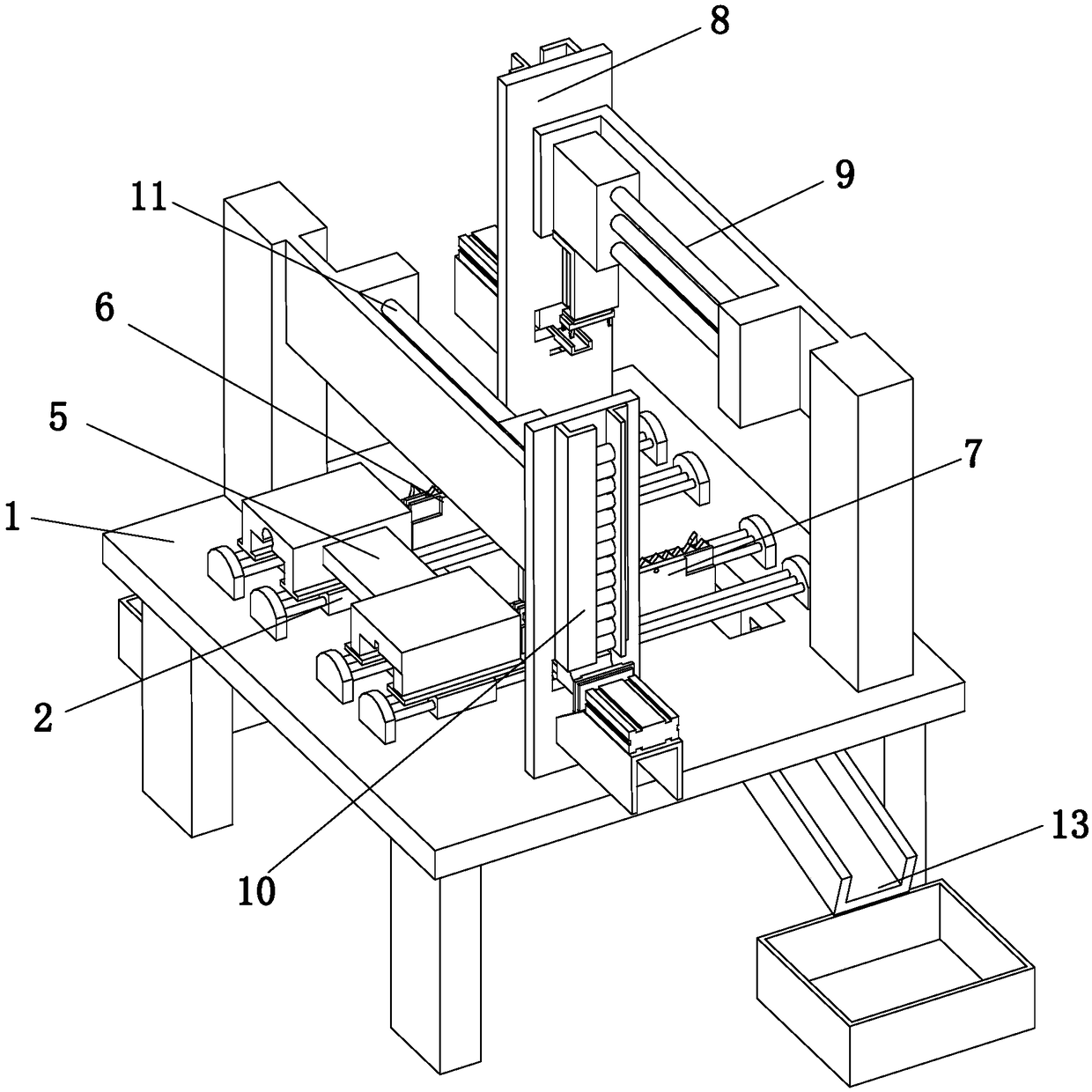
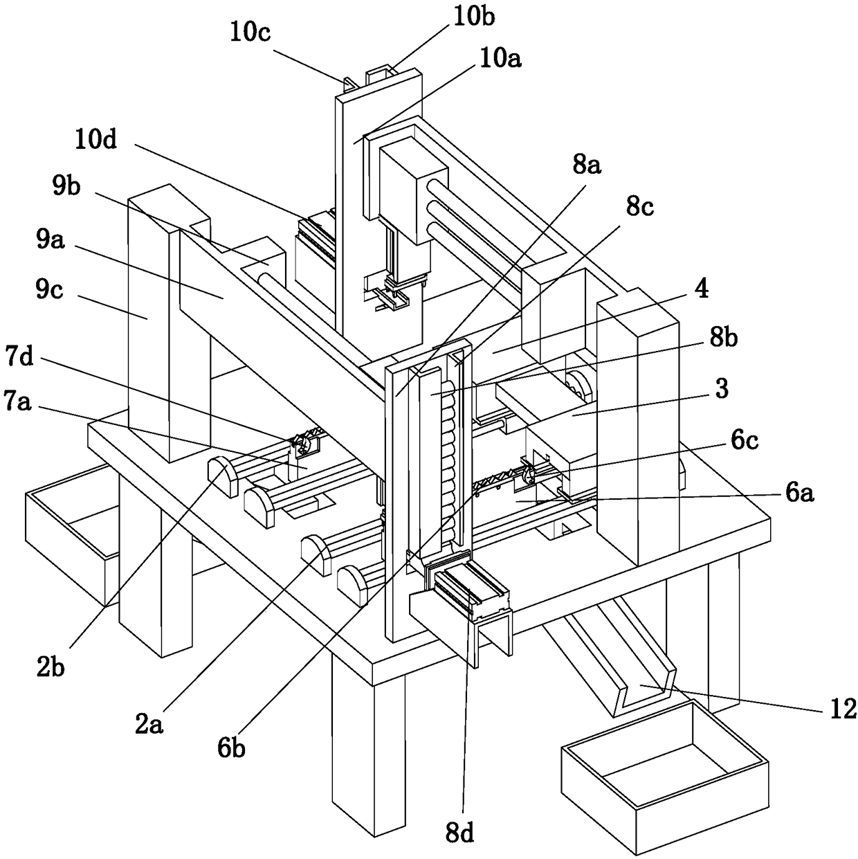
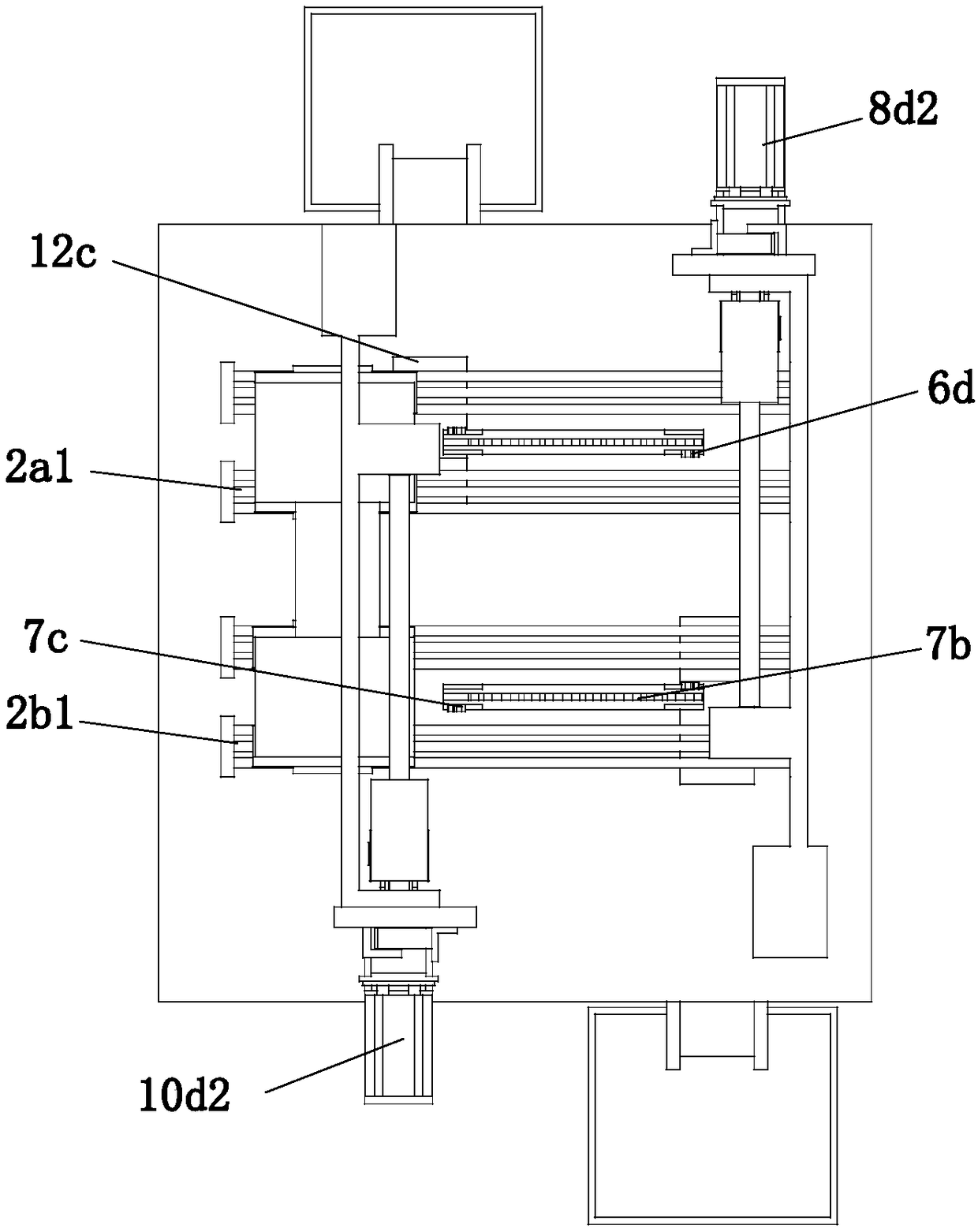
[0037] refer to Figure 1 to Figure 11 The cylinder lock automatic slotting machine shown includes a workbench 1 arranged horizontally, the top of the workbench 1 is provided with a slotting mechanism 2 arranged along its length direction, and the slotting mechanism 2 includes a The top of the first driving device 2a and the second driving device 2b arranged along its length direction, the tops of the first driving device 2a and the second driving device 2b are respectively provided with the first bearing block 3 and the first bearing block 3 fixedly connected with it. Two bearing blocks 4, a connecting block 5 is arranged between the first bearing block 3 and the second bearing block 4, and the two ends of the connecting block 5 are respectively fixedly connected with the first bearing block 3 and the second bearing block 4, The first driving device 2a and the second driving device 2b can respectively drive the first bearing block 3 and the second bearing block 4 to reciproca...

Embodiment 2

[0057] The grooving process of the automatic grooving machine for the lock cylinder includes the following steps:

[0058] Step 1. Stack the cylinders to be slotted in the first feeding device 8 and the second feeding device 10 respectively;

[0059]Step 2, the first transfer device 9 sends the lock cylinder in the first feeding device 8 to the first bearing block 3, and the first driving device 2a drives the first bearing block 3 to reciprocate along the length direction of the workbench 1 , the middle of the first driving device 2a is provided with a first slotting device 6 arranged along its length direction, the first bearing block 3 moves forward, and the first slotting device 6 slots the first cylinder , after the slotting is completed, when the first bearing block 3 returns, the first blocking assembly 6d on the first slotting device 6 collides with the contour edge of the lock cylinder, and the lock bladder is blanked into the first blanking device 12;

[0060] Step 3...


PUM


Abstract

The invention relates to the lock container machining field, in particular to an automatic slot broaching machine for a lock container. The automatic slot broaching machine comprises a horizontally arranged workbench; the top of the workbench is provided with a slotting mechanism which comprises a first driving device and a second driving device; the tops of the first driving device and the seconddriving device are provided with a first bearing block and a second bearing block correspondingly; a connection block is arranged between the first bearing block and the second bearing block; a firstslot broaching device is arranged at the middle position of the first driving device; a second slot broaching device is arranged at the middle position of the second driving device; a first feeding device is arranged on one side of the first driving device; a first moving and transporting device is arranged on the side wall of the first feeding device; a second feeding device is arranged on one side of the second driving device; a second moving and transporting device is arranged on the side wall, close to the second driving device, of the second feeding device; and the bottom of the workbench is provided with a first discharging device and a second discharging device. The automatic slot broaching machine is high in automation degree, the slot broaching efficiency of the lock container isimproved, the process design is ingenious, and 2 / 3 manual work is saved.

Description

technical field [0001] The invention relates to the field of lock cylinder processing equipment and processing technology, in particular to a lock cylinder automatic slotting machine and a slotting process thereof. Background technique [0002] With the improvement of people's living standards and the strengthening of people's awareness of prevention, various forms of locks can be seen in people's lives. They can be hidden locks fixed on doors, boxes, bags and other objects, or they can be hung on The padlock used on the buckle fixed on the object, and most of the locks are divided into two parts, one part is a gutless lock, this kind of lock has no lock core, which is easy to be damaged, lacks safety, and is not easy to use; the other part is a guttural lock , this kind of lock is a structured lock cylinder, which has higher safety performance and is not easy to be damaged than a gallbladder lock. It is the first choice in people's life. The lock cylinder is one of the indi...

Claims


Application Information

Patent Timeline
IPC IPC(8): B23D37/02B23D41/06B23D41/08B23Q1/25B23Q5/40
CPCB23D37/02B23D41/06B23D41/08B23Q1/25B23Q5/40
Inventor 曾国强
Owner 浙江慕来智能科技有限公司
Learn More