Hydraulic speed regulating valve and hydraulic system

A speed control valve and hydraulic technology, which is applied in the direction of fluid pressure actuators, servo motors, servo motor components, etc., can solve the problems of heavy workload of self-made speed control valves, and achieve simple structure, high flow control accuracy, and convenient adjustment Effect

Active Publication Date: 2018-06-22
WUHAN MARINE MACHINERY PLANT
View PDF9 Cites 7 Cited by
  • Summary
  • Abstract
  • Description
  • Claims
  • Application Information

AI Technical Summary

Problems solved by technology

[0006] In order to solve the problems in the prior art that the flow rate of the commercially available speed regulating valve is fixed and the workload of the self-made speed regulating valve is large, the embodiment of the present invention provides a hydraulic speed regulating valve and a hydraulic system

Method used


Image

  • Hydraulic speed regulating valve and hydraulic system
  • Hydraulic speed regulating valve and hydraulic system
  • Hydraulic speed regulating valve and hydraulic system

Examples


Embodiment 1

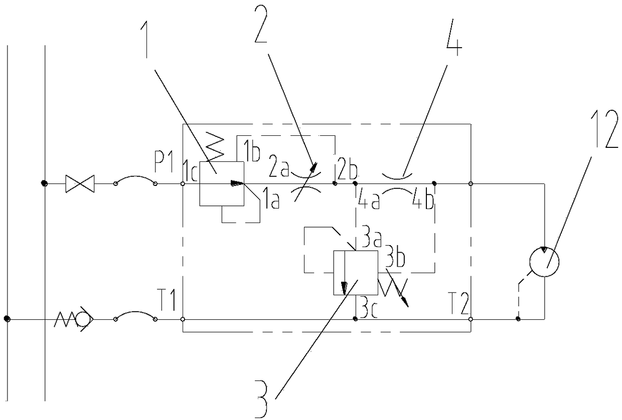
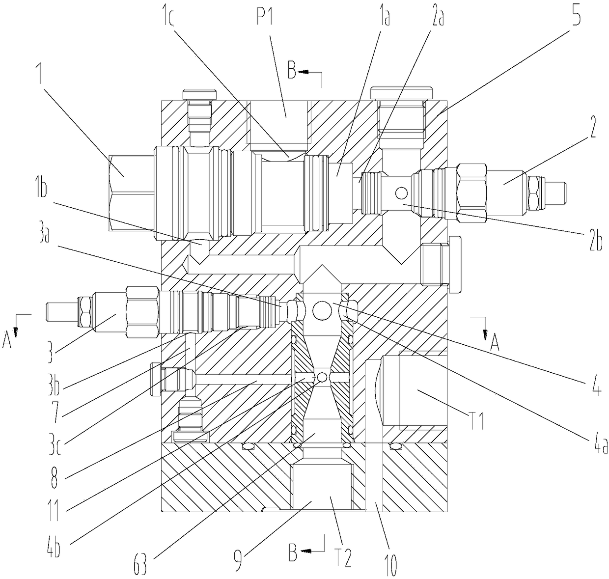
[0027] The embodiment of the present invention provides a hydraulic speed regulating valve, such as figure 1 As shown, the hydraulic speed control valve is suitable for the portable pump drive motor 12 in the hydraulic submersible pump system. The hydraulic speed control valve includes: a pressure reducing valve 1, a throttle valve 2, an overflow valve 3 and a venturi tube 4. The oil outlet 1a of the pressure reducing valve 1 communicates with the oil inlet 2a of the throttle valve 2, the oil drain 1b of the reducing valve 1 communicates with the oil outlet 2b of the throttle valve 2, and the oil inlet of the relief valve 3 3a is connected with the oil outlet 2b of the throttle valve 2, the oil outlet 2b of the throttle valve 2 is also connected with the oil inlet 4a of the Venturi tube 4, and the control oil port 3b of the relief valve 3 is connected with the Venturi tube 4 Throat 4b (see figure 2 ) Is connected, the opening pressure of the overflow valve 3 satisfies the formu...

Embodiment 2

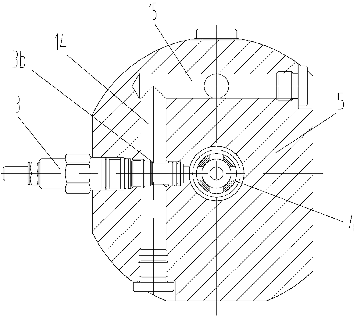
[0041] The embodiment of the present invention provides a hydraulic system, such as Figure 5 As shown, a portable pump drive motor 12 and a concentric tube 13 are included. The concentric tube includes an inner tube 13a and an outer tube 13b. The outer diameter of the inner tube 13a is smaller than the inner diameter of the outer tube 13b, and the outer tube 13b is sleeved outside the inner tube 13a, The oil inlet of the portable pump drive motor 12 communicates with the inner tube 13a of the concentric tube 13, and the oil return port of the portable pump drive motor 12 communicates with the cavity between the outer tube 13b and the inner tube 13a of the concentric tube 13. Combine figure 1 with figure 2 As shown, the hydraulic system also includes: a pressure reducing valve 1, a throttle valve 2, an overflow valve 3, and a venturi tube 4. The oil outlet 1a of the pressure reducing valve 1 communicates with the oil inlet 2a of the throttle valve 2, the oil drain 1b of the re...


PUM


Abstract

The invention discloses a hydraulic speed regulating valve and a hydraulic system, and belongs to the field of hydraulic valve assemblies. The hydraulic speed regulating valve comprises a pressure reducing valve, a throttling valve, an overflow valve and a Venturi tube; an oil outlet of the pressure reducing valve communicates with an oil inlet of the throttling valve; an oil drainage port of thepressure reducing valve communicates with an oil outlet of the throttling valve; an oil inlet of the overflow valve communicates with the oil outlet of the throttling valve; the oil outlet of the throttling valve communicates with an oil inlet of the Venturi tube; a control oil port of the overflow valve communicates with the throat of the Venturi tube; and opening pressure of the overflow valve meets a formula as shown in the specification. The hydraulic speed regulating valve is little in pressure loss, and the hydraulic oil flow accurately adjusted by the hydraulic speed regulating valve isthe same as the rated flow of a portable pump driving motor.

Description

Technical field [0001] The invention relates to the field of hydraulic valve groups, in particular to a hydraulic speed regulating valve and a hydraulic system. Background technique [0002] The hydraulic submersible pump system is an important supporting equipment for chemical tankers, oil tankers and floating production storage and offloading (FPSO, Floating Production Storage and Offloading), and is mainly used for the loading and unloading of liquid cargo products. In the hydraulic submersible pump system, the role of the portable pump set is mainly used as an emergency pump set when the submersible pump fails. Portable pump sets include portable pump heads, concentric hoses and accessories, and portable pump heads include portable pump motors, impellers and pump casings. Among them, the speed control valve is fixedly installed on the deck, the portable pump head is placed in the cargo hold, and the portable pump head is connected to the speed control valve through concentri...

Claims


Application Information

Patent Timeline
Patent Type & Authority Applications(China)
IPC IPC(8): F15B13/02F15B11/00
CPCF15B11/00F15B13/02F15B2013/002
Inventor 洪威方敏
Owner WUHAN MARINE MACHINERY PLANT
Why Eureka
Try Eureka