Mechanical sealing device and application thereof

A mechanical sealing device and technology of the sealing device, which are applied in the direction of engine sealing, mechanical equipment, engine components, etc., can solve the problems of short service life, uneven force on the sealing surface, fragile main sealing surface, etc., to improve the use of Longevity, reduced friction, and the effect of small frictional resistance

Active Publication Date: 2018-06-22
上海康晟航材科技股份有限公司
View PDF9 Cites 2 Cited by
  • Summary
  • Abstract
  • Description
  • Claims
  • Application Information

AI Technical Summary

Problems solved by technology

These technologies and methods have more or less deficiencies, some have low sealing reliability, and some have short service life and potential safety hazards
The oil seal is easy to age, the friction force of the sealing surface is large, it is easy to wear, and it is easy to fail. The main sealing surface of the existing mechanical seal is fragile, and the distribution spring is used to provide the retention force of the sealing surface. The failure rate of the sealing surface is uneven, and the failure rate is mainly used for auxiliary static sealing. O-ring high pressure area is prone to rolling failure

Method used


Image

  • Mechanical sealing device and application thereof
  • Mechanical sealing device and application thereof
  • Mechanical sealing device and application thereof

Examples


Embodiment Construction

[0033] In order to describe the technical content of the present invention more clearly, further description will be given below in conjunction with specific embodiments.

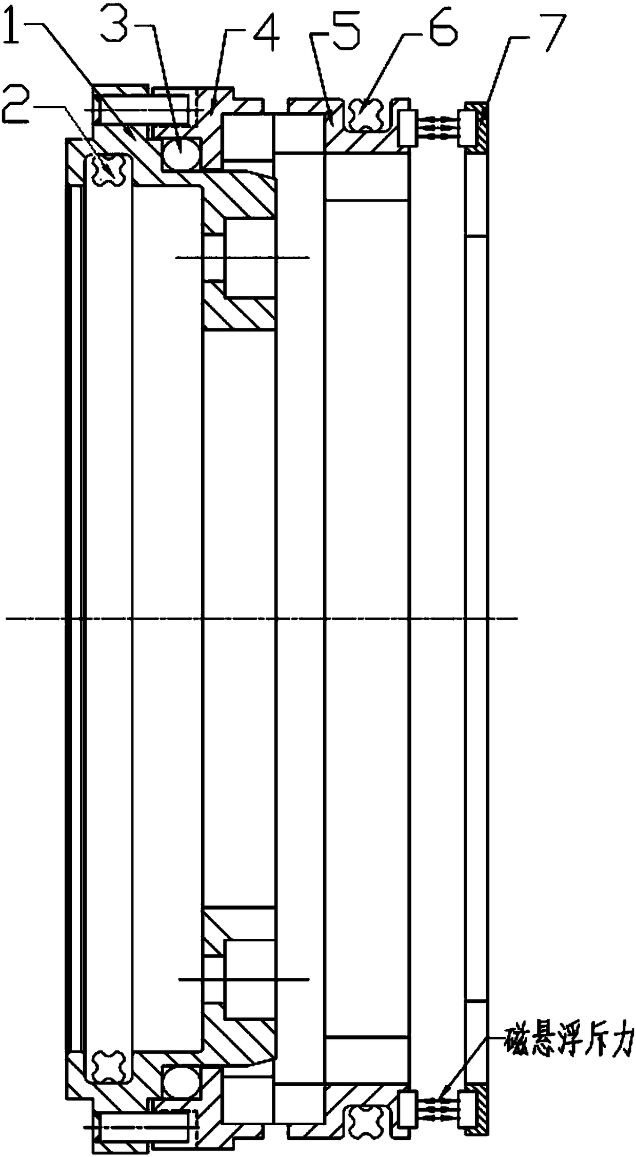
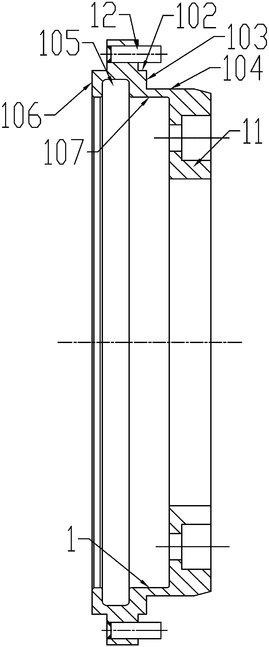
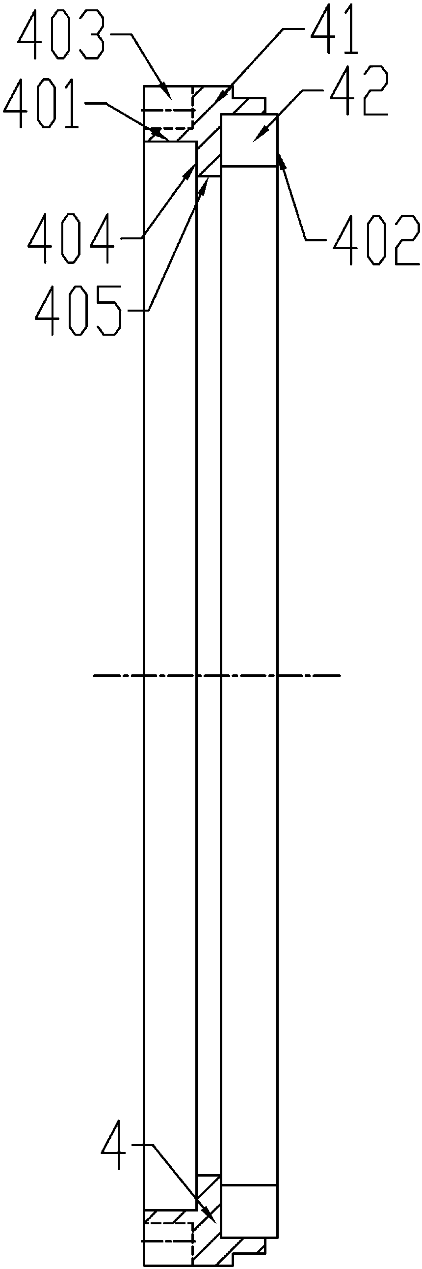
[0034] like figure 1 , 2 , 5, and 7 show an embodiment of a mechanical sealing device provided by the present invention. The mechanical sealing device includes: a positioning sleeve 1, including a positioning sleeve body 11, an outer mounting surface 104, and a shaft for fitting the roller shaft to be sealed. The inner mounting surface 107, and the first sealing groove 105 arranged on the inner mounting surface 107 and equipped with the first sealing ring 2 inside, through the first sealing ring 2, the positioning sleeve 1 and the to-be The sealed roller shaft forms the first static sealing body; the dynamic friction ring 4 includes an assembly surface 401 forming a second sealing groove with the outer mounting surface of the positioning sleeve, and a first dynamic sealing surface protruding axially along ...


PUM


Abstract

The invention relates to a mechanical sealing device. The sealing device comprises a positioning sleeve, a moving friction ring, a fixed friction ring and a stop ring, wherein the positioning sleeve comprises a positioning sleeve body, an outer mounting surface, an inner mounting surface which is used for mounting a roll shaft to be sealed in a sleeving manner, and a first sealing groove which isformed in the inner mounting surface, wherein a first sealing ring is assembled in the first sealing groove; the moving friction ring comprises an assembling surface which forms a second sealing groove with the outer mounting surface of the positioning sleeve, and a first moving sealing surface which is protruded in the axial direction of a main body of the moving friction ring; a second sealing ring is arranged in the second sealing groove; the fixed friction ring comprises a first end of a second moving sealing surface corresponding to the first moving sealing surface of the moving frictionring and a second end which is provided with a permanent magnet ring; and the stop ring comprises a permanent magnet repulsion ring corresponding to the second end of the fixed friction ring, so thata magnetic levitation repulsion pair is formed between the fixed friction ring and the stop ring. By adopting the mechanical sealing device and application thereof provided by the invention, the structure is refined; and the convenience in installation, regulation, use and maintenance is improved.

Description

technical field [0001] The invention relates to the field of mechanical seals, in particular to a mechanical seal device and its application. Background technique [0002] At present, in the technical field of dynamic sealing of slab continuous casting rolls and slab electromagnetic stirring rolls, commonly used dynamic sealing structures include: radial oil seal, rotary seal, and axial mechanical seal. These technologies and methods are more or less deficient, and some have low sealing reliability, and some have short service life and potential safety hazards. The oil seal is easy to age, the friction force of the sealing surface is large, it is easy to wear, and it is easy to fail. The main sealing surface of the existing mechanical seal is fragile, and the distribution spring is used to provide the retention force of the sealing surface. The failure rate of the sealing surface is uneven, and the failure rate is mainly used for auxiliary static sealing. The high pressure ...

Claims


Application Information

Patent Timeline
Patent Type & Authority Applications(China)
IPC IPC(8): F16J15/16F16J15/32
CPCF16J15/16F16J15/32
Inventor 汪晶乔志洪王艳芳
Owner 上海康晟航材科技股份有限公司
Why Eureka
Try Eureka