Vacuum pressure control valve

A vacuum pressure and control valve technology, which is applied in the direction of valve lift, valve details, valve device, etc., can solve problems such as wrong action and inability to judge the actual position of the valve core, so as to improve accuracy, ensure reliability and stability, and improve response sexual effect

Pending Publication Date: 2018-06-22
苏州欧纳克纳米科技有限公司
View PDF0 Cites 4 Cited by
  • Summary
  • Abstract
  • Description
  • Claims
  • Application Information

AI Technical Summary

Problems solved by technology

Especially when the compressed air cannot be supplied normally, the actual position of the spool cannot be judged, which may lead to malfunction

Method used


Image

  • Vacuum pressure control valve
  • Vacuum pressure control valve

Examples


Embodiment Construction

[0039] The present invention will now be described in further detail with reference to the drawings. These drawings are all simplified schematic diagrams, which merely illustrate the basic structure of the present invention in a schematic manner, so they only show the structures related to the present invention.

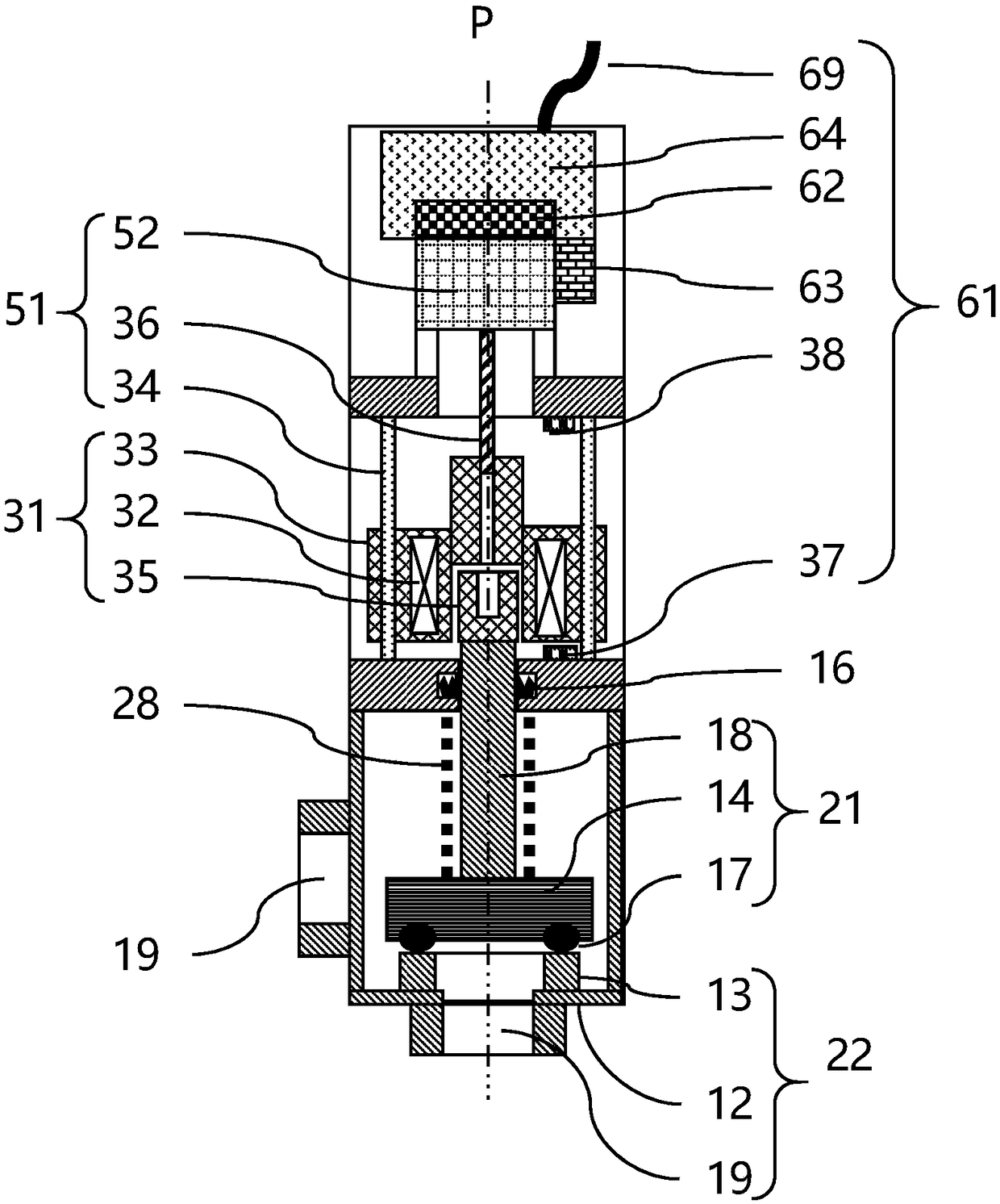
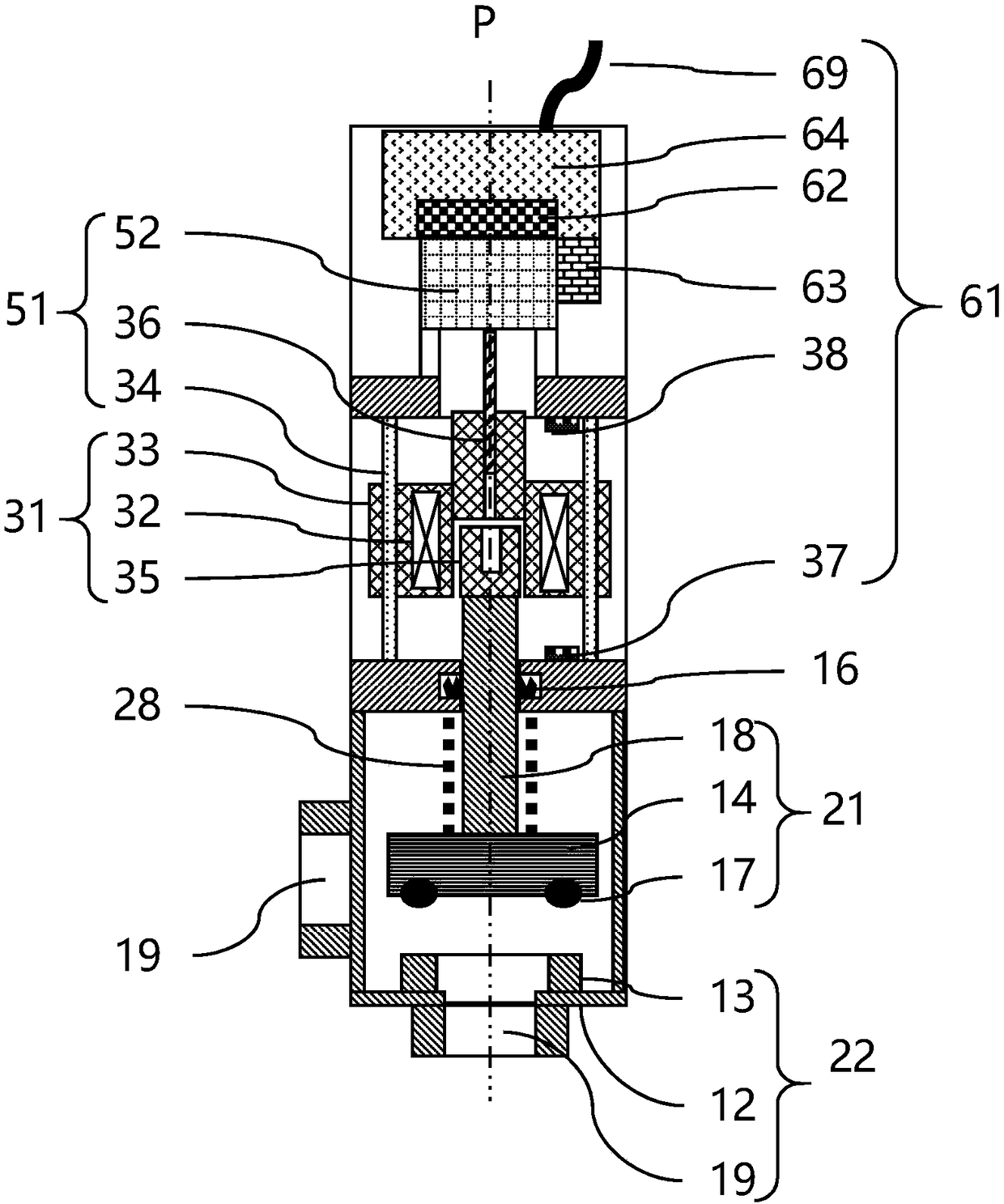
[0040] Such as figure 1 , figure 2 As shown, a vacuum pressure control valve includes:

[0041] The valve body 12 is formed with a valve cavity. The valve body 12 has at least two ports 19 for communicating the valve cavity with the outside. In the valve cavity, a valve seat 13 is provided at a position corresponding to at least one of the ports 19;

[0042] The valve core 21 includes a valve plate 14 and a valve stem 18 that are fixedly connected,

[0043] The coupler 31, the coupler 31 includes a bracket 33, an armature 35 and a coil 32 fixed on the bracket 33, and

[0044] The opening actuator 51 is used to drive the bracket 33 of the coupler 31 to move up and down,

[00...


PUM


Abstract

The invention relates to a lifting type pressure control valve with an isolating function used in vacuum equipment. A vacuum pressure control valve includes a valve body, a valve cavity is formed in the valve body which is provided with at least two joints which can enable the valve cavity to communicate with the outside, and the position, corresponding to at least one of the joints, in the valvecavity is provided with a valve seat; a valve core includes a valve plate and a valve rod which are fixedly connected with each other, a coupler includes a support and a coil and an armature which arefixed to the support, an opening actuator is used for driving a support of the coupler to move up and down, and the coupler is arranged above the valve body; and the valve core is arranged in the valve cavity, the valve plate is matched with the valve seat, and the valve rod penetrates through the valve body to be fixedly connected with the armature arranged above the valve body. According to thevacuum pressure control valve, the flow can be precisely regulated in the wide conductance range through a pure electric connection system, thereby realizing the precise pressure control, and achieving isolating and emergency power-lossing protection; and the vacuum pressure control valve is suitable for the exhausting control and the process pressure control from barometric pressure to lower middle vacuum.

Description

Technical field [0001] The invention relates to a lifting pressure control valve with isolation function used in vacuum equipment. Background technique [0002] In the semiconductor manufacturing process, sometimes high-speed vacuum pressure control is required, sometimes fast and accurate pressure control with a wide conductance range is required, sometimes high sealing performance is required when the valve is closed, and the system needs to be safely shut down in case of sudden power failure. Isolate upstream and downstream pipelines. [0003] In the semiconductor manufacturing process, the following proposal is proposed: a pressure control valve with isolation function (hereinafter referred to as a control valve) is installed between the vacuum chamber as a vacuum container and the vacuum pump, and the vacuum chamber is exhausted or stopped. So as to control the internal pressure of the vacuum chamber close to the required vacuum pressure. [0004] In semiconductor manufacturin...

Claims


Application Information

Patent Timeline
Patent Type & Authority Applications(China)
IPC IPC(8): F16K27/02F16K1/36F16K1/42F16K1/46F16K31/04F16K37/00
CPCF16K27/0209F16K1/36F16K1/42F16K1/46F16K31/046F16K37/0041
Inventor 蒋健伟孙志鹏
Owner 苏州欧纳克纳米科技有限公司
Why Eureka
Try Eureka