Novel mechanical ammeter

A mechanical and electric meter technology, applied in the field of new mechanical electric meters, can solve the problems of large measurement deviation, poor overall effect, counting error and other problems of mutual inductance electric meters, and achieve the effect of perfect function, strong practicability, and reduction of measurement deviation

Active Publication Date: 2018-06-22
浙江星皓科技股份有限公司
View PDF8 Cites 0 Cited by
  • Summary
  • Abstract
  • Description
  • Claims
  • Application Information

AI Technical Summary

Problems solved by technology

[0004] In the above process, due to the conversion of electric energy to the rotation of the counter, the counting error is caused by factors such as friction torque. At the same time, the traditional way of reading the electric quantity is to multiply the electric quantity displayed by the counter by the ratio of the mutual inductance, which leads to a large measurement deviation of the mutual inductance electric meter. not effectively

Method used


Image

  • Novel mechanical ammeter
  • Novel mechanical ammeter

Examples


Embodiment Construction

[0015] The present invention will be further described below in conjunction with the accompanying drawings and preferred embodiments.

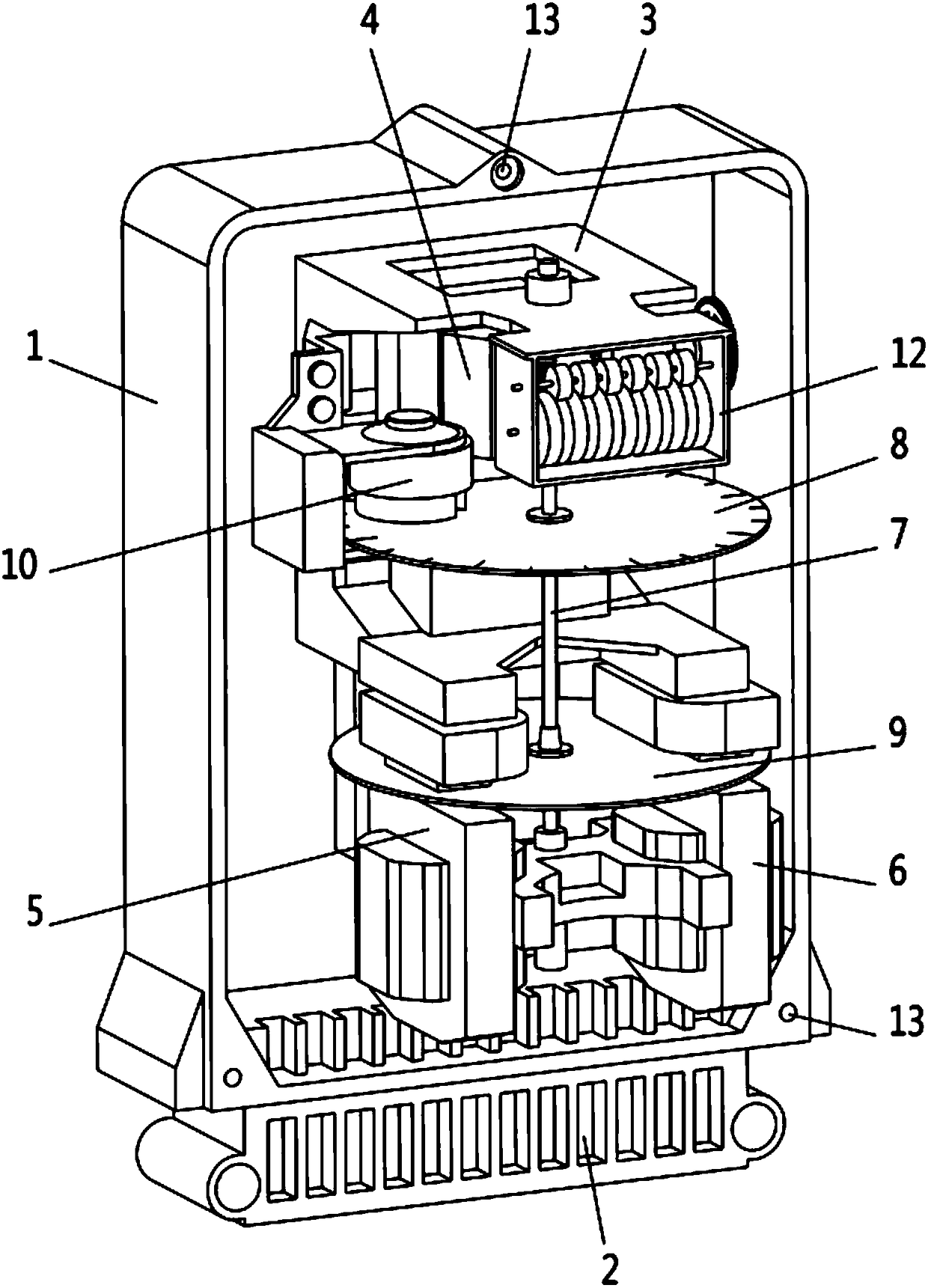
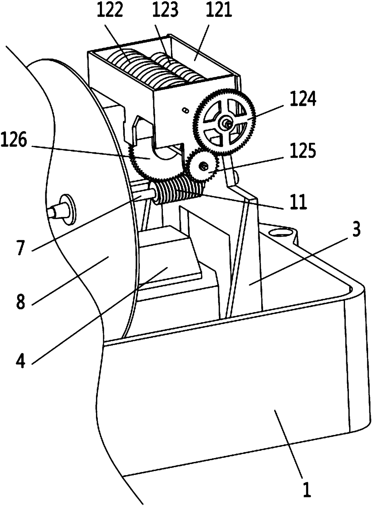
[0016] Such as figure 1 and figure 2 As shown, a new type of mechanical electric meter involved in this embodiment includes a bottom case 1, a terminal hole 2 is provided on the bottom case 1, a support 3 is provided inside the bottom case 1, and a first A transformer 4, a second transformer 5 and a third transformer 6 are arranged in parallel on the lower part of the support 3, a rotating shaft 7 is connected to the support 3, and an upper aluminum disc 8 and a lower aluminum disc are arranged on the rotating shaft 7 disc 9, the upper aluminum disc 8 is set on the first transformer 4, the lower aluminum disc 9 is set on the second transformer 5 and the third transformer 6, and the upper aluminum disc 8 is set There is a braking permanent magnet 10 affixed to the support 3, the upper end of the rotating shaft 7 is provided with a threaded c...


PUM


Abstract

The invention discloses a novel mechanical ammeter. The novel mechanical ammeter includes a bottom housing; wiring terminal holes are formed in the bottom housing; a supporting seat is arranged in thebottom housing; a first mutual inductor is arranged on an upper part of the supporting seat; a second mutual inductor and a third mutual inductor are arranged on a lower part of the supporting seat in parallel; a rotation shaft is rotatably connected to the supporting seat; an upper aluminum round plate and a lower aluminum round plate are arranged on the rotation shaft; the upper aluminum roundplate is arranged on the first mutual inductor; the lower aluminum round plate is arranged on the second mutual inductor and the third mutual inductor; a brake permanent magnet fixedly connected to the supporting seat is arranged on the upper aluminum round plate; a threaded column is arranged on an upper end of the rotation shaft; a mechanical counter is arranged on the upper part of the supporting seat; the mechanical counter includes a counting rack, a counting plate, a counting gear, a first transmission gear, a second transmission gear, and a third transmission gear; and the third transmission gear is drivingly connected to the threaded column. The mechanical meter is small in metering errors, is easy to read, is perfect in function, and is high in practicability.

Description

technical field [0001] The invention relates to a mechanical counter device, in particular to a novel mechanical electric meter. Background technique [0002] Most of the existing electricity meters are digital display meters, but mechanical meters are also used in some regions or countries. Mechanical meters still have their unique advantages in high temperature and high humidity areas. In a specific area, it has many advantages such as high accuracy, good stability, and long life. [0003] The usual way to read the electricity of a three-phase four-wire mutual inductance watt-hour meter is to multiply the counter reading by the ratio of mutual inductance. Because the main structure of a mechanical watch is composed of a voltage coil and a current coil (that is, a transformer), a rotating shaft, a brake magnet, a gear, a counter, and the like. The working principle of the mechanical watt-hour meter is: when the meter is connected to the circuit under test, an alternating ...

Claims


Application Information

Patent Timeline
Patent Type & Authority Applications(China)
IPC IPC(8): G01R11/16
CPCG01R11/16
Inventor 庄建新杨爽王施强
Owner 浙江星皓科技股份有限公司
Why Eureka
Try Eureka