Testing method and device of direct current electronic transformer delay time

An electronic transformer and delay time technology, which is applied in the direction of measuring devices, instruments, and measuring electrical variables, can solve the problems of inability to detect phase offsets, inability to distinguish periodic changes in AC signals, and inability to calculate delay times between signals.

Active Publication Date: 2018-06-22
ELECTRIC POWER RES INST OF GUANGDONG POWER GRID
View PDF8 Cites 4 Cited by
  • Summary
  • Abstract
  • Description
  • Claims
  • Application Information

AI Technical Summary

Problems solved by technology

[0004] However, because this method cannot distinguish the periodic changes of AC signals, it cannot detect the phase shift in different periodic signals, that is, it cannot calculate the delay time between signals under different periods, so it has defects in tech

Method used


Image

  • Testing method and device of direct current electronic transformer delay time
  • Testing method and device of direct current electronic transformer delay time
  • Testing method and device of direct current electronic transformer delay time

Examples


Embodiment Construction

[0051] The embodiment of the present invention provides a method and device for testing the delay time of a DC electronic transformer, which provides complete theoretical and technical support for testing the delay time of a DC electronic transformer in the current field of DC power transmission.

[0052] In order to make the purpose, features and advantages of the present invention more obvious and understandable, the technical solutions in the embodiments of the present invention will be clearly and completely described below in conjunction with the accompanying drawings in the embodiments of the present invention. Obviously, the following The described embodiments are only some, not all, embodiments of the present invention. Based on the embodiments of the present invention, all other embodiments obtained by persons of ordinary skill in the art without making creative efforts belong to the protection scope of the present invention.

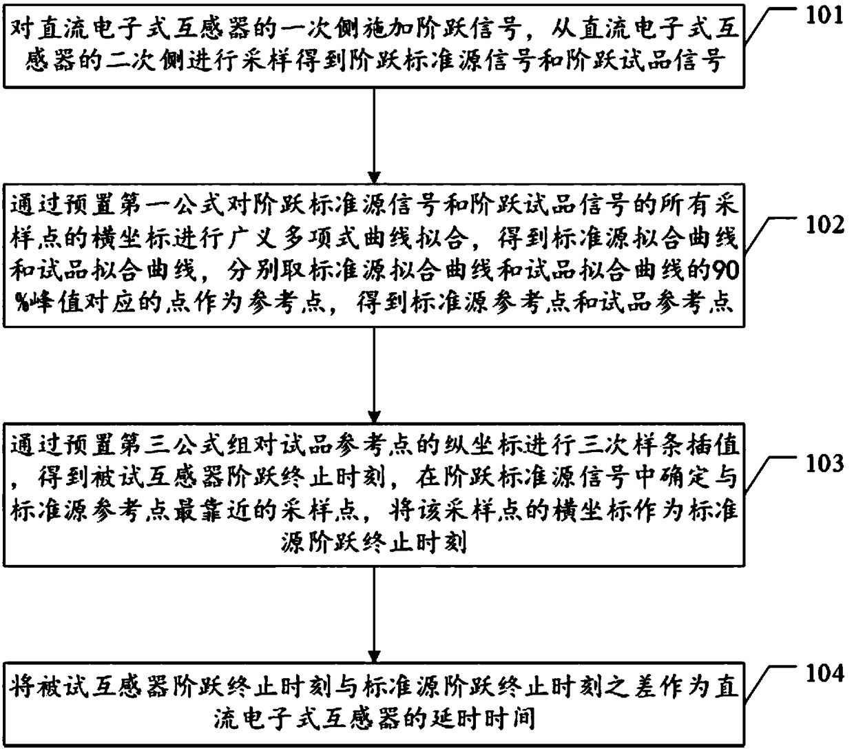
[0053] see figure 1 , an embodiment of ...


PUM


Abstract

The invention provides a testing method and a testing device of direct current electronic transformer delay time. The method includes steps of applying a step signal to a primary side of a direct current electronic transformer; sampling a secondary side of the direct current electronic transformer to obtain a step standard source signal and a step test product signal; performing a generalized multi-item curve fitting on the step standard source signal and the step test product signal, and acquiring a standard source fitting curve and a test product fitting curve; taking points corresponding to90% of peak values of the standard source fitting curve and the test product fitting curve as reference points; acquiring a standard source reference point and a test product reference point; performing cubic spline interpolation on a longitudinal coordinate of the test product reference point to obtain a step termination moment of a tested transformer; confirming a sampling point which is closest to the standard source reference point in the step standard source signal, and using a cross coordinate of the sampling point as the standard source step termination moment; using the difference between the step termination moment of the tested transformer and the standard source step termination moment as the delay time of the direct current electronic transformer.

Description

technical field [0001] The invention relates to the technical field of DC electronic transformers, in particular to a method and device for testing the delay time of DC electronic transformers. Background technique [0002] The DC electronic transformer is an important primary equipment for the construction and operation of the DC transmission system. It generally uses digital output to provide voltage and current signals for the bay layer equipment, which inevitably involves the delay time of signal transmission. The delay of the DC electronic transformer is the time delay difference between the actual primary electrical quantity collected by the DC transformer and converted into a digital message output. It is one of the core indicators that the control and protection equipment that needs real-time processing is extremely concerned about. The DC transmission control and protection system has extremely high requirements for real-time performance. If the delay time of DC ele...

Claims


Application Information

Patent Timeline
IPC IPC(8): G01R35/02
CPCG01R35/02
Inventor 王红星盛超张健肖磊石陈晓科骆潘钿杨汾艳刘正富朱良合唐酿黄辉余超耘罗强
Owner ELECTRIC POWER RES INST OF GUANGDONG POWER GRID
Why Eureka
Try Eureka