Wafer transfer method and device

A wafer and vertical technology, applied in the direction of transportation and packaging, conveyor objects, electrical components, etc., can solve the problem of low transmission capacity and achieve the effect of high transmission capacity

Active Publication Date: 2020-04-28
BEIJING SEMICORE PRECISION MICROELECTRONICS EQUIP CO LTD
View PDF5 Cites 0 Cited by
  • Summary
  • Abstract
  • Description
  • Claims
  • Application Information

AI Technical Summary

Problems solved by technology

However, the transfer throughput of existing wafer transfer devices and wafer transfer methods is low

Method used

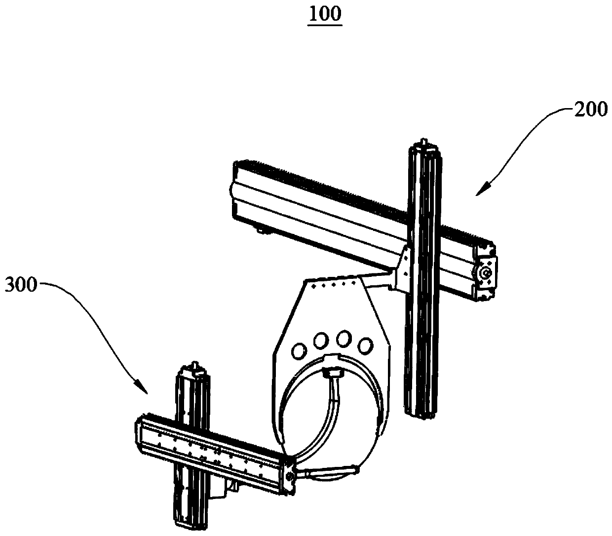
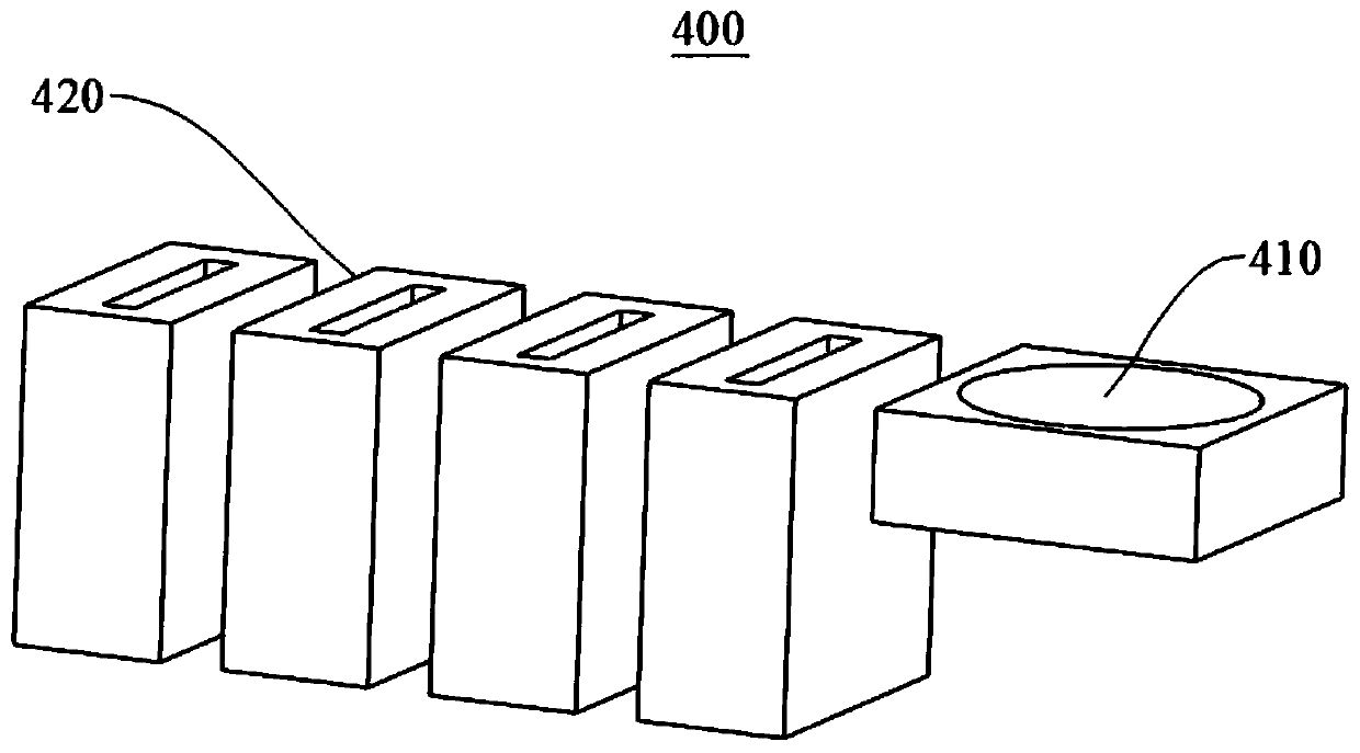
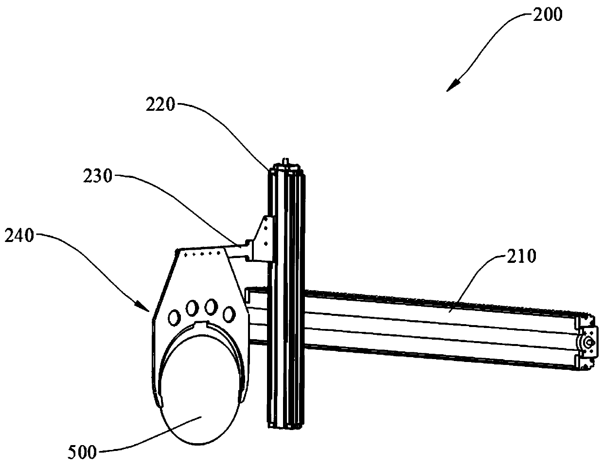

Image

  • Wafer transfer method and device
  • Wafer transfer method and device
  • Wafer transfer method and device

Examples


Embodiment Construction

[0026] In order to make the purposes, technical solutions and advantages of the embodiments of the present invention clearer, the technical solutions in the embodiments of the present invention will be clearly and completely described below with reference to the accompanying drawings in the embodiments of the present invention. Obviously, the described embodiments These are some embodiments of the present invention, but not all embodiments. The components of the embodiments of the invention generally described and illustrated in the drawings herein may be arranged and designed in a variety of different configurations.

[0027] Thus, the following detailed description of the embodiments of the invention provided in the accompanying drawings is not intended to limit the scope of the invention as claimed, but is merely representative of selected embodiments of the invention. Based on the embodiments of the present invention, all other embodiments obtained by those of ordinary ski...


PUM


Abstract

The invention relates to the field of single wafer cleaning equipment, in particular to a method and device for transporting a wafer. According to the method, the wafer is grabbed through a grab structure; the wafer is transported to a preset position; the wafer is clamped out from the grab structure through a turnover structure and the angle of the wafer is adjusted, so that the angle of the wafer is consistent with that of a process groove; and the wafer is put into the process groove through the turnover structure, so that transportation of the wafer in the process grooves of different directions and angles is achieved. According to the method, the wafer transporting capacity is high.

Description

technical field [0001] The present invention relates to the field of single-wafer cleaning equipment, and in particular, to a method and device for transferring wafers. Background technique [0002] Wafer cleaning equipment consists of multiple process tanks, each tank is responsible for a cleaning process, such as ultrasonic / megasonic cleaning tank, brushing tank, drying tank, etc. In order to achieve a given process effect, the setting directions and angles of each groove body are different. For example, there are horizontal ones and vertical ones. The processing process of each wafer may pass through these directions and angles. Processing of the same process slot. However, placing the wafers into the process cells in different orientations presents a technical challenge. [0003] The existing wafer transfer device clamps the wafer through the opening and closing of the pick-up arm and the air gripper. The opening and closing of the air gripper is realized by the air cy...

Claims


Application Information

Patent Timeline
Patent Type & Authority Patents(China)
IPC IPC(8): H01L21/67H01L21/677
CPCH01L21/6704H01L21/67796
Inventor 史霄舒福璋陶利权熊朋
Owner BEIJING SEMICORE PRECISION MICROELECTRONICS EQUIP CO LTD
Why Eureka
Try Eureka