Battery module bracket, battery module and battery pack

A technology of battery modules and battery packs, which is applied in the direction of battery/battery traction, battery/fuel cell control devices, battery pack components, etc., and can solve problems affecting the service life of battery packs, low space utilization, and large temperature differences between batteries, etc. problems, to achieve the effect of simple structure, improved service life, and reduced temperature difference

Active Publication Date: 2020-11-27
湖南科霸汽车动力电池有限责任公司
View PDF6 Cites 0 Cited by
  • Summary
  • Abstract
  • Description
  • Claims
  • Application Information

AI Technical Summary

Problems solved by technology

The battery pack is generally formed by fixing the battery module in the casing. At present, when the battery pack is assembled into a battery module, it usually adopts a two-layer structure, with air flowing in from the middle and flowing out from the upper and lower sides. However, this structural space utilization The low efficiency leads to low energy density, and there are also multi-layer (3 layers and above) structures. This structure is easy to cause uneven heat dissipation due to the different airflows entering each layer and the initial temperature of the airflow. The temperature difference between the body batteries is large, which affects the service life of the battery pack

Method used


Image

  • Battery module bracket, battery module and battery pack
  • Battery module bracket, battery module and battery pack
  • Battery module bracket, battery module and battery pack

Examples


Embodiment 1

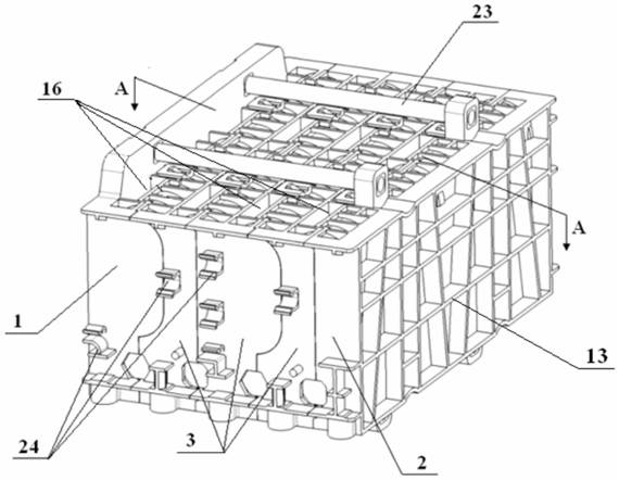
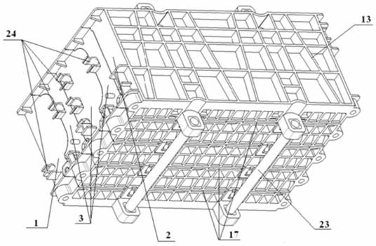
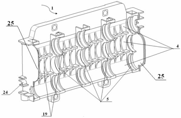
[0026] A battery module bracket, such as figure 1 , figure 2 As shown, it includes a left bracket 1, a right bracket 2 and three middle brackets 3;

[0027] As shown in Figure 3 (a), one side of the left bracket 1 is provided with three layers of first ventilation slots 4 that are curved in side view, and each layer of first ventilation slots 4 is provided with four first ventilation slots 4 that are curved in side view. A battery pack support slot 5, a first groove 19 is arranged in the first ventilation slot 4 of the left bracket 1, and the positions of the first battery pack support slots 5 provided on the first ventilation slot 4 of each layer are the same, and the first battery pack The arc diameter of the support groove 5 is matched with the outer diameter of the single battery in the corresponding battery pack, the arc diameter of the first ventilation slot 4 is larger than the arc diameter of the first battery pack support slot 5, and the arc diameter of the first ve...

Embodiment 2

[0032] A battery module bracket, the structure of which is similar to that of the battery module bracket in Embodiment 1, the difference is that the number of the intermediate brackets is five.

Embodiment 3

[0034] A battery module, including twelve groups of battery groups formed by connecting the same number of single cells in series, installing twelve groups of battery groups in the battery group installation channel in the battery module bracket in embodiment 1, twelve The battery packs are connected in series with each other, and the wiring harnesses of the twelve battery packs are clamped in the wire slots in the battery module bracket.


PUM


Abstract

The invention provides a battery module bracket, which includes a left bracket, a right bracket and at least one middle bracket, the left bracket, at least one middle bracket, and the right bracket are mated and fitted together in sequence, and the corresponding battery pack support grooves are mutually Matching and merging to form a battery pack installation channel, the corresponding ventilation slots are matched with each other to form an air flow channel. There are several air inlets on the top of the uppermost air flow channel, and several air outlets on the bottom of the lowermost air flow channel. The air outlets are provided with several air outlets between adjacent two layers of airflow channels, and the air inlets, air outlets, and air outlets are matched one by one. At the same time, a battery module using the battery module bracket of the present invention and a battery pack including the battery module are also provided. The battery module bracket of the present invention has simple and novel structure, convenient installation and disassembly, good heat dissipation effect, low temperature difference between individual cells in the battery module, and can prolong the service life of the battery pack.

Description

technical field [0001] The invention relates to a battery module bracket, a battery module and a battery pack using the same. Background technique [0002] For the automotive power battery device that uses a cylindrical battery pack, that is, the battery pack, a large amount of heat will be generated during use, so the heat dissipation of the battery pack needs to be considered. The battery pack is generally formed by fixing the battery module in the casing. At present, when the battery pack is assembled into a battery module, it usually adopts a two-layer structure, with air flowing in from the middle and flowing out from the upper and lower sides. However, this structural space utilization The low efficiency leads to low energy density, and there are also multi-layer (3 layers and above) structures. This structure is easy to cause uneven heat dissipation due to the different airflows entering each layer and the initial temperature of the airflow. The temperature differenc...

Claims


Application Information

Patent Timeline
Patent Type & Authority Patents(China)
IPC IPC(8): H01M2/10H01M10/613H01M10/625H01M10/6561B60L50/64H01M50/249
CPCH01M10/613H01M10/625H01M10/6561B60L58/26H01M50/20Y02T10/70Y02E60/10
Inventor 刘丹钟发平吴纯华陈馨魏力群储爱华
Owner 湖南科霸汽车动力电池有限责任公司
Why Eureka
Try Eureka