New energy charging pile device

A charging pile and new energy technology, applied in charging stations, coupling devices, two-component connection devices, etc., can solve the problems of casualties, charging interruption, single setting mode, etc., and achieve the effect of reducing potential safety hazards.

Inactive Publication Date: 2018-06-22
广州大正机械科技开发有限公司
View PDF6 Cites 2 Cited by
  • Summary
  • Abstract
  • Description
  • Claims
  • Application Information

AI Technical Summary

Problems solved by technology

Charging piles are supporting facilities for new energy vehicles and are carriers for charging new energy vehicles. However, the traditional charging piles have a single setting mode, and the charging process only depends on the friction force when the charging terminal and the charging part are plugged in to keep the state. If you accidentally touch the charging terminal or be affected by the pulling of the charging cable, it may cause the charging terminal to fall off, causing charging interruption. In addition, traditionally, the conductive sheet in the charging part is generally placed relatively outside. This kind of conductive sheet is easy to be contacted by metal sheet or metal rod. Therefore, when a person who lacks safety awareness inserts the metal sheet or metal rod into the charging terminal, an electric shock accident is likely to occur, which is likely to cause casualties. big security risk

Method used


Image

  • New energy charging pile device
  • New energy charging pile device
  • New energy charging pile device

Examples


Embodiment Construction

[0022] All features disclosed in this specification, or steps in all methods or processes disclosed, may be combined in any manner, except for mutually exclusive features and / or steps.

[0023] Any feature disclosed in this specification (including any appended claims, abstract and drawings), unless expressly stated otherwise, may be replaced by alternative features which are equivalent or serve a similar purpose. That is, unless expressly stated otherwise, each feature is one example only of a series of equivalent or similar features.

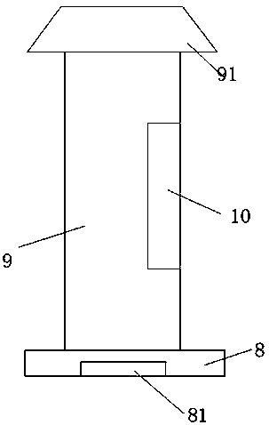
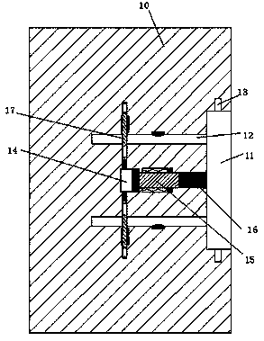
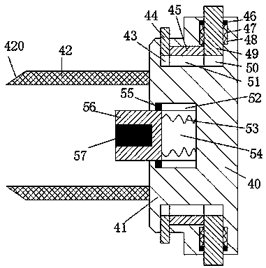
[0024] Such as Figure 1 to Figure 4As shown, a new energy charging pile device of the device of the present invention includes a charging pile body 9, a charging terminal 10 disposed in the right end surface of the charging pile body 9, and a charging terminal 40 connected to a new energy vehicle, The bottom of the charging pile body 9 is fixed with a base 8, and the inner bottom of the base 8 is provided with a counterweight 81, and the sta...


PUM


Abstract

The invention discloses a new energy charging pile device. The new energy charging pile device comprises a charging pile body, a charging end part and a charging end, wherein the charging end part isarranged in an end surface of a right side of the charging pile body, the charging end is connected with a new energy automobile, a notch is formed in a right end surface of the charging end part andis provided with a rightward opening, locking cavities are correspondingly formed in an upper end wall and a lower end wall of the notch, jacks are vertically and correspondingly formed in a left endwall of the notch, a first sliding cavity is formed in the left end wall of the notch and is arranged between the two jacks, first sliding grooves are correspondingly formed in left sides of an upperend wall and a lower end wall of the first sliding cavity and penetrate through the jacks, a second sliding groove is formed in a right end wall of the first sliding cavity and communicates with the notch, a first magnet is arranged in the first sliding cavity and can slide leftwards and rightwards, a sliding plate is arranged in the first sliding groove and can slide upwards and downwards, a second magnet is fixedly arranged on an end surface, facing the first sliding cavity, of the sliding plate, and a power connection sheet is fixedly arranged on an end surface, facing the first sliding cavity, of the sliding plate.

Description

technical field [0001] The invention relates to the field of new energy vehicles, in particular to a new energy charging pile device. Background technique [0002] New energy vehicles are gradually replacing traditional vehicles with many advantages such as energy saving, environmental protection and pollution-free, and are widely used. Charging piles are supporting facilities for new energy vehicles and are carriers for charging new energy vehicles. However, the traditional charging piles have a single setting mode, and the charging process only depends on the friction force when the charging terminal and the charging part are plugged in to keep the state. If you accidentally touch the charging terminal or be affected by the pulling of the charging cable, it may cause the charging terminal to fall off, causing charging interruption. In addition, traditionally, the conductive sheet in the charging part is generally placed relatively outside. This kind of conductive sheet ...

Claims


Application Information

Patent Timeline
IPC IPC(8): H01R13/703H01R13/639H01R24/00B60L11/18
CPCB60L53/16H01R13/639H01R13/703H01R24/00Y02T10/70Y02T10/7072Y02T90/14
Inventor 聂值清
Owner 广州大正机械科技开发有限公司
Why Eureka
Try Eureka