
Long-handle cleaning tool

A technology of cleaning tools and long handles, applied in cleaning equipment, manufacturing tools, cleaning machinery, etc., can solve problems such as affecting normal use, low stability, and damage to mop discs.

Pending Publication Date: 2018-06-29
HEBEI JIESHIBAO DAILY PLASTIC PROD CO LTD
View PDF13 Cites 4 Cited by
  • Summary
  • Abstract
  • Description
  • Claims
  • Application Information

AI Technical Summary

Problems solved by technology

[0004] 1. The mop rod generally includes an upper connecting rod and a lower connecting rod socketed in the upper connecting rod. In order to prevent the relative sliding of the upper connecting rod and the lower connecting rod during normal use of the mop, the upper connecting rod and the lower connecting rod There is often a locking structure, but the locking structure in the prior art is more complicated and inconvenient to use
Chinese patent CN202568131U discloses "a telescopic mop rod". The fastening device adopts the cooperation of the handle and the elastic collar to loosen and clamp the sleeve rod by opening and closing the handle. The handle of the mop rod is hinged with the elastic collar , the handle is provided with a clip against the sleeve rod, and the elastic collar is provided with a gap for the clip to pass through. When the handle is closed, the clip presses against the sleeve rod to make it tightly connected with the elastic collar. The axial direction is perpendicular to the expansion and contraction direction of the sleeve rod, so when the force is exerted on the clip when the telescopic rod is dragged, a force will be exerted on the clip. The arc-shaped groove and the arc-shaped protrusion matching the arc-shaped groove on the handle have a complex structure, which cannot be stably fastened over time, and the service life is not long;
[0005] 2. The rotation between the mop rod and the mop disc is mostly 180°, that is, front and rear or left and right rotations. The rotation method is not flexible, and it is not suitable for cleaning in a narrow range.
Chinese patent "ZL201510439842.1" discloses "a universal mop head", which includes a connecting sleeve, a mop head body and a connecting ball, the first connecting column on the inner side of the lower end of the connecting sleeve and the front and rear sides of the connecting ball The first connection hole on the left and right sides of the connecting ball is connected by rotation, and the second connection column on the left and right sides of the connection ball is connected by rotation to the second connection hole on the top of the mop head body, thereby realizing a 360° rotation between the connection sleeve and the mop head body, but the first Rotating the connecting post and the second connecting post for a long time will cause the surface to be worn, resulting in low stability when fastened with the first connecting hole and the second connecting hole, thereby increasing the scrap rate of the product;
[0006] 3. The various parts of the mop plate are generally locked by screws and nuts. After the mop plate is assembled, it is not easy to disassemble, so it is difficult to clean the mop plate separately; The disk is easily damaged due to impact, and any damage to the mop disk in the prior art will cause the entire panel to be scrapped, thereby increasing the cost of use;
[0007] 4. Since the two ends of the mop cloth are sleeved on the two ends of the base plate, long-term use for mopping the floor and spinning and washing will cause the two ends of the wipe cloth to fall off the base plate, affecting normal use

Method used


Image

  • Long-handle cleaning tool
  • Long-handle cleaning tool
  • Long-handle cleaning tool

Examples


Embodiment

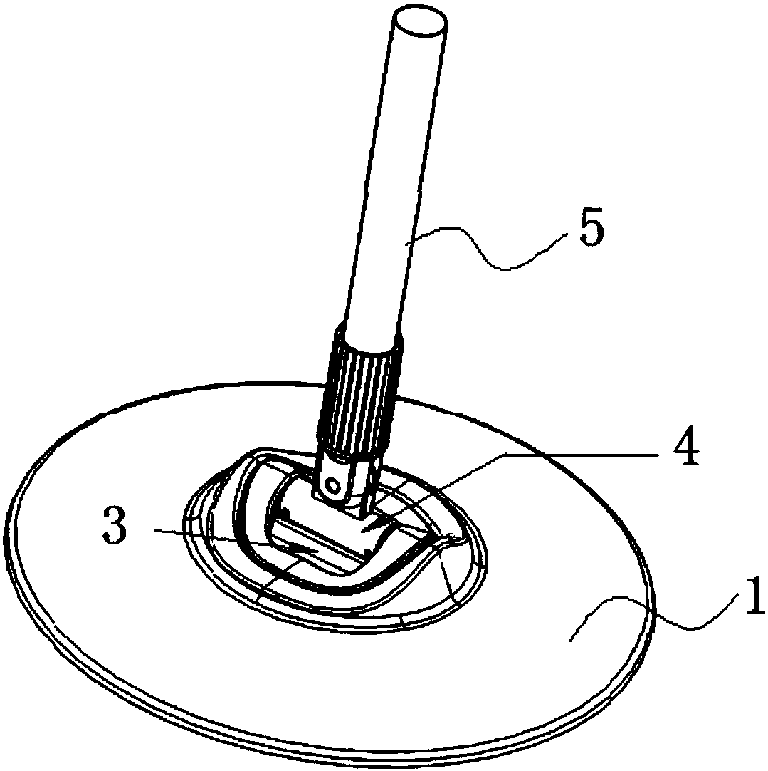
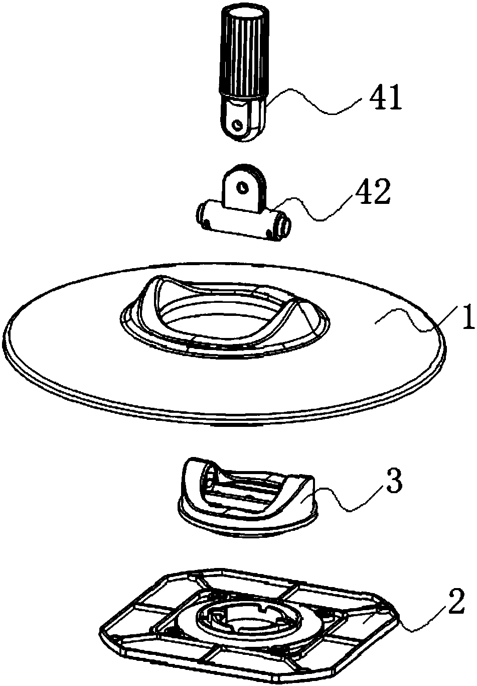
[0090] Embodiment: a long-handled cleaning tool, such as Figure 1-Figure 28 As shown, it includes a panel, a connecting seat 3 and a telescopic rod 5, the connecting seat is fixed on the panel, and the telescopic rod is located on the upper side of the panel;

[0091] It also includes a rotary joint 4, the rotary joint includes a first rotary part 41 and a second rotary part 42, the first rotary part 41 is rotatably connected to the second rotary part 42, and the second rotary part 42 can Rotationally connected to the connecting seat 3, the rotating shaft of the first rotating member 41 and the rotating shaft of the second rotating member 42 are perpendicular to each other, the first rotating member is connected to the telescopic rod, and the wiping cloth is located on the side of the panel. lower side;

[0092] The telescopic rod 5 includes an outer rod body 51 and an inner rod body 52, the outer rod body 51 and the inner rod body 52 are socketed, and a locking structure 6 ...


PUM


Abstract

The invention discloses a long-handle cleaning tool, which comprises a panel, a connecting seat and a telescopic rod, and further comprises a rotational joint, wherein the rotational joint comprises afirst rotary piece and a second rotary piece; the first rotary piece is rotatably connected to the second rotary piece; the second rotary piece is rotatably connected to the connecting seat; a rotating shaft of the first rotary piece is perpendicular to a rotating shaft of the second rotary piece; the first rotary piece is connected to the telescopic rod; a wiping rag is arranged at the lower side of the panel; the telescopic rod comprises an outer rod body and an inner rod body; and the outer rod body and the inner rod body mutually sleeve. According to the long-handle cleaning tool providedby the invention, a locking structure of the telescopic rod is simple; moreover, convenient angle adjusting and locating can be achieved between the telescopic rod and the panel, so as to adapt to various cleaning angles during cleaning; therefore, the long-handle cleaning tool is applicable to a mop and other cleaning tools having similar requirements; and in addition, the wiping rag is effectively fixed to a base plate of the mop by a lower panel via a fixing claw, so that the service life of the mop is prolonged.

Description

technical field [0001] The invention belongs to the technical field of cleaning supplies, in particular to a long-handled cleaning tool. Background technique [0002] The mop is a cleaning tool commonly used in homes, small offices and commercial places to scrub the floor. The mop is generally composed of a mop rod, a mop disc and a connector connecting the mop rod and the mop disc. The mop disc is divided into a round mop disc and a flat mop disc. . [0003] There is following problem in the mop sold in the market at present: [0004] 1. The mop rod generally includes an upper connecting rod and a lower connecting rod socketed in the upper connecting rod. In order to prevent the relative sliding of the upper connecting rod and the lower connecting rod during normal use of the mop, the upper connecting rod and the lower connecting rod Locking structures are often provided at places, but the locking structures in the prior art are complicated and inconvenient to use. Chine...

Claims


Application Information

Patent Timeline
Patent Type & Authority Applications(China)
IPC IPC(8): A47L13/20A47L13/42A47L13/256B25G1/04
CPCA47L13/20A47L13/256A47L13/42B25G1/04
Inventor 任海燕
Owner HEBEI JIESHIBAO DAILY PLASTIC PROD CO LTD
Learn More