Gravel separating and drying device

A drying device and sand and gravel separation technology, applied in the directions of drying gas arrangement, solid separation, drying, etc., can solve the problems of difficult separation and low drying efficiency, save time, improve drying efficiency, and avoid frequent cleaning of the device Effect

Active Publication Date: 2018-06-29
HAIMEN DADE INTPROP SERVICE CO LTD
View PDF8 Cites 1 Cited by
  • Summary
  • Abstract
  • Description
  • Claims
  • Application Information

AI Technical Summary

Problems solved by technology

[0004] The purpose of the present invention is to provide a sand separation and drying device t

Method used


Image

  • Gravel separating and drying device
  • Gravel separating and drying device

Examples


Embodiment Construction

[0017] The following is further described in detail through specific implementation methods:

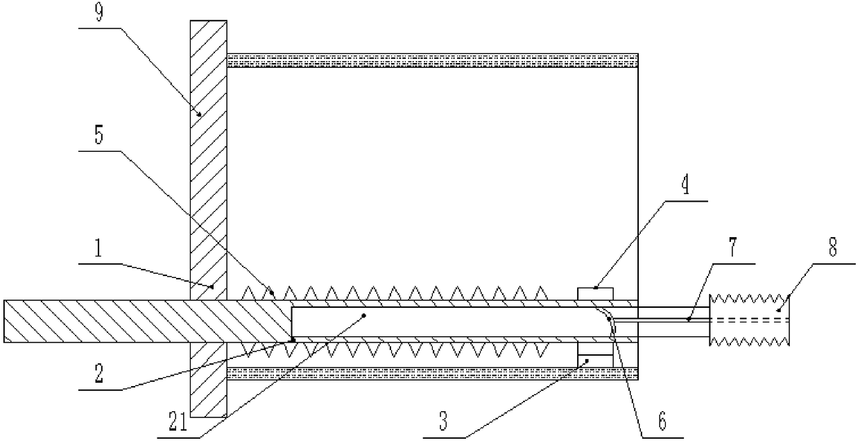
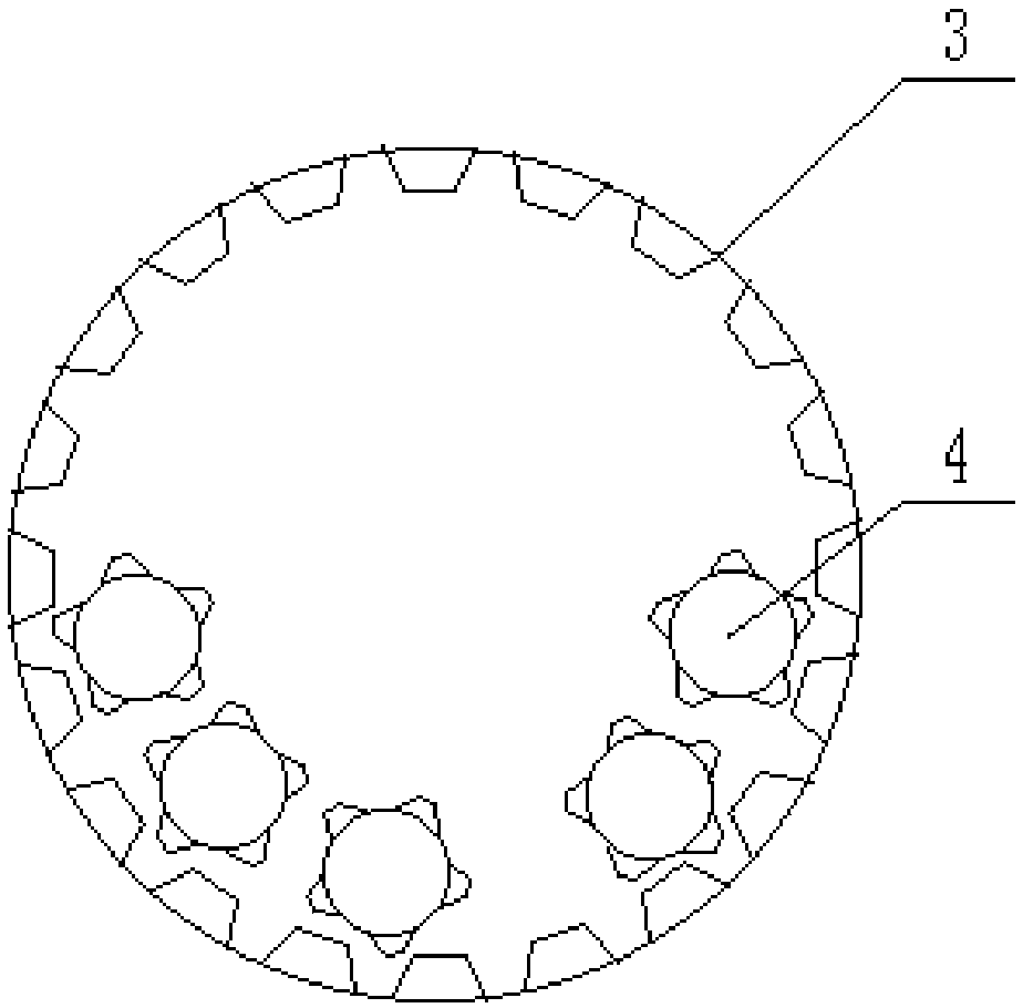
[0018] The reference signs in the accompanying drawings of the specification include: trommel 1, rotating roller 2, air intake groove 21, ring gear 3, gear 4, protrusion 5, spiral groove 6, mast 7, telescopic cover 8, bottom plate 9.

[0019] Such as figure 1 As shown, the sand and gravel separation and drying device includes a frame on which a rotating motor is fixed, and a trommel 1 is connected to rotate on the frame, and a belt for transmission is connected between the outer wall of the trommel 1 and the output shaft of the rotating motor; The left end of the sieve 1 is connected with a disc-shaped bottom plate 9, and the right end of the trommel 1 is connected with a cover plate, and the cover plate and the bottom plate 9 are fixed on the frame, such as figure 2 As shown, the lower side of the base plate 9 is provided with a plurality of through holes, and the connecting line ...


PUM


Abstract

The invention belongs to the field of building engineering, and particularly discloses a gravel separating and drying device. A rack is connected with a rotary screen, a rotary motor which is used fordriving the rotary screen to rotate is further fixed on the rack, a bottom plate is further fixed on the rack, and the rotary screen is rotatably connected with the bottom plate; the inner wall of the rotary screen is fixedly connected with an inner gear ring, the lower portion of the bottom plate is rotatably connected with rotating rolls, the rotating rolls penetrate through the bottom plate, and a gear which is engaged with the inner gear ring is arranged on the outer wall of each rotating roll in a sleeving manner; a plurality of projections are arranged on the outer wall of each rotatingroll, the end, which is away from the bottom plate, of each rotating roll is connected with a telescopic cover, an electric heating wire is wound on each telescopic cover, an air inlet hole is formedin each telescopic cover, and a one-way valve is arranged in each air inlet hole; and an air inlet groove which communicates with the corresponding telescopic cover is further formed in the end surface, which is away from the bottom plate, of each rotating roll, an air outlet hole which communicates with the corresponding air inlet groove is further formed in the outer wall of each rotating roll,and an air outlet one-way valve is arranged in each air outlet hole. By the scheme, gravels are dried while being separated, two processes are combined, the time is saved, and the efficiency is improved.

Description

technical field [0001] The invention belongs to the field of construction engineering and specifically discloses a sand and gravel separation and drying device. Background technique [0002] On the construction site, it is often necessary to use a large amount of sand and gravel. The raw materials of sand and gravel are generally obtained from rivers and other places. , generally use a sieve to separate the mixed sand and stones, and then use them separately. Because the sand and gravel raw materials contain a lot of water, and the sand is easy to agglomerate and adhere to the screen when it encounters water, so the agglomerated sand is not easy to be sieved out during the separation process with the sieve, resulting in incomplete separation. On the one hand, it causes The waste of sand, on the one hand, the sand is mixed in the stone, which affects the subsequent utilization of the stone. And the screen cannot work for a long time, and it is necessary to constantly clean ...

Claims


Application Information

Patent Timeline
IPC IPC(8): B07B1/22B02C4/08F26B21/00
CPCB02C4/08B07B1/22F26B21/001
Inventor 王宏伟
Owner HAIMEN DADE INTPROP SERVICE CO LTD
Why Eureka
Try Eureka