Tube part cutting device

A technology for cutting devices and pipe parts, applied in the direction of pipe shearing devices, shearing devices, metal processing machinery parts, etc., can solve the problems of irregular cutting sections and uneven force on the surface of pipe fittings, and achieve the effect of improving safety

Inactive Publication Date: 2018-06-29
重庆市长寿区维凤商贸有限公司
View PDF7 Cites 5 Cited by
  • Summary
  • Abstract
  • Description
  • Claims
  • Application Information

AI Technical Summary

Problems solved by technology

[0004] The present invention intends to provide a cutting device for pipe parts to solve the problem that the surface of pipe parts is su

Method used


Image

  • Tube part cutting device
  • Tube part cutting device

Examples


Embodiment Construction

[0018] The present invention will be described in further detail below by means of specific embodiments:

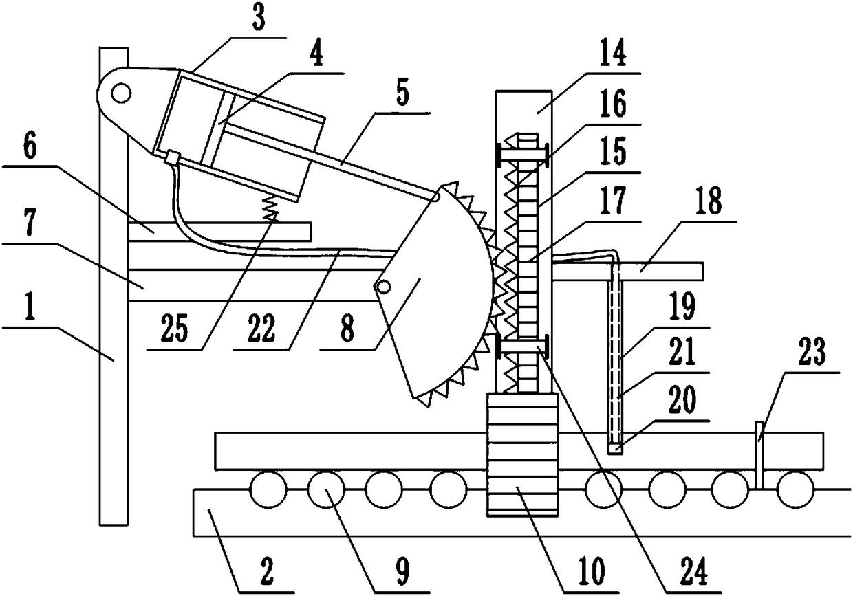
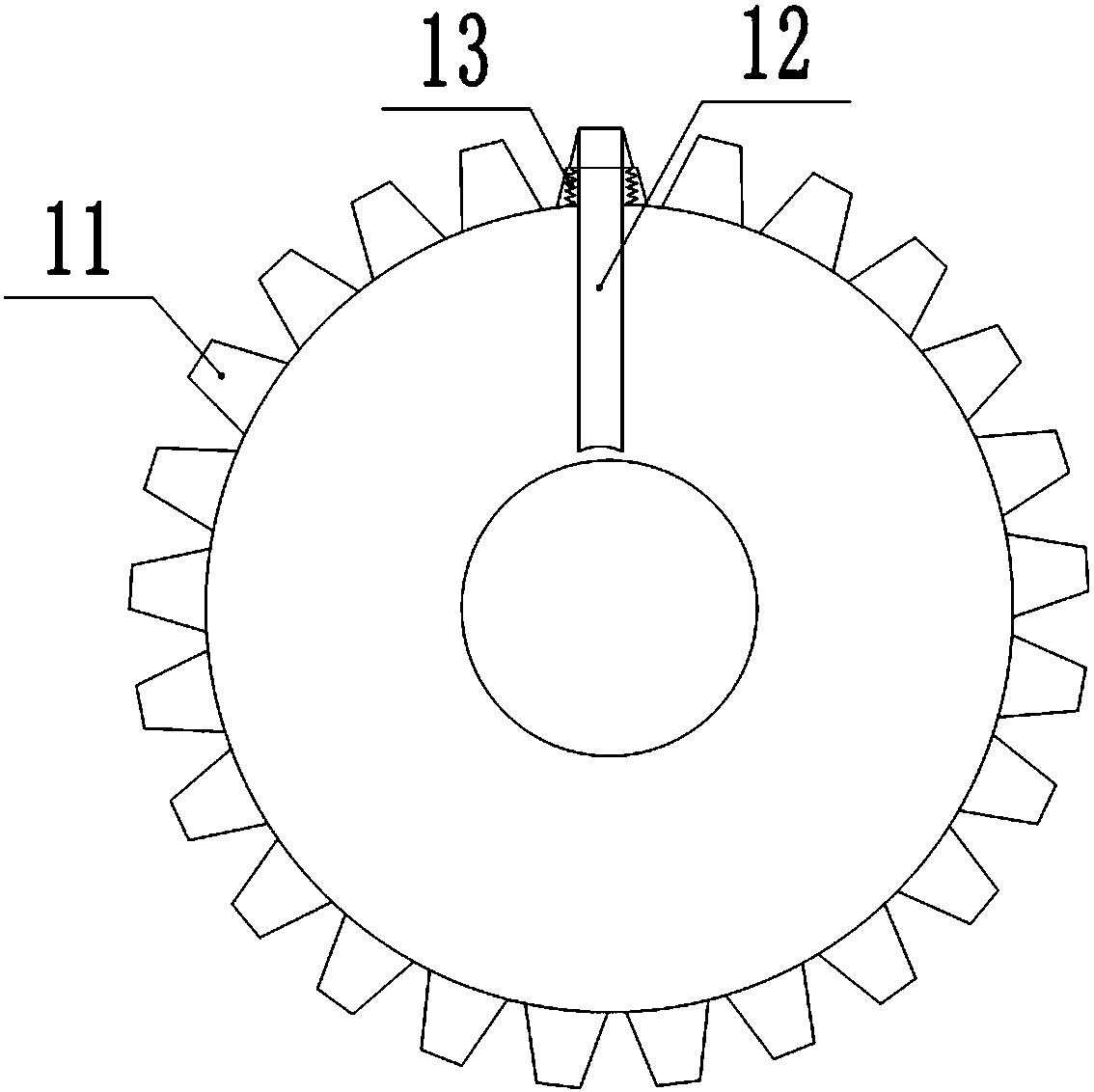
[0019] The reference signs in the drawings of the description include: frame 1, workbench 2, cylinder 3, slide plate 4, connecting rod 5, first support plate 6, second support plate 7, sector gear 8, support roller 9, clamp Holding gear 10, driving tooth 11, pressing rod 12, telescopic spring 13, vertical plate 14, rack 15, first gear part 16, second gear part 17, horizontal plate 18, cutter bar 19, cutter head 20, guide Air pipe 21, air outlet pipe 22, infrared emitter 23, fixing ring 24, support spring 25.

[0020] The embodiment is basically as figure 1 Shown: a pipe parts cutting device, including a frame 1 and a workbench 2, the frame 1 is located on one side of the workbench 2, a driving mechanism is provided on the frame 1, and the driving mechanism includes a rotating connection on the frame 1 The cylinder 3 is provided with an air outlet, the cylinder 3 is slid...


PUM


Abstract

The invention relates to a tube part cutting device. The tube part cutting device comprises a rack and a worktable, wherein an air cylinder is arranged on the rack, a sliding plate is slidably connected in the air cylinder, a connecting rod is fixed to the sliding plate, a fan-shaped gear is rotatably connected to a second supporting plate on the rack, and the end, far from the sliding plate, of the connecting rod is rotatably connected to the fan-shaped gear; a supporting roller is rotatably connected to the worktable, a clamping gear is also rotatably connected to the worktable, a through hole is formed in the middle of the clamping gear, a stretchable driving gear is arranged on the clamping gear, the driving gear is fixedly connected to a leaning rod, a telescopic spring is arranged inthe driving gear, a vertical plate is also fixedly connected to the worktable, a rack is slidably connected to the vertical plate, a first grinding tooth part and a second grinding tooth part are arranged on the rack, a transverse plate is fixedly connected to the vertical plate, a cutter bar is fixedly connected to the transverse plate, a tool bit is arranged at the bottom end of the cutter bar,a gas guide pipe is arranged in the cutter bar, an air jet hole is formed in the cutter bar, and an air outlet pipe is connected between the gas guide pipe and the air outlet. The tube part cutting device provided by the invention solves the problem that the cutting section of a tube part is irregular.

Description

technical field [0001] The invention relates to the field of cutting devices, in particular to a cutting device for pipe parts. Background technique [0002] Machine element, also known as machine part, is the basic element of machinery, and it is an inseparable single part that makes up machinery and machines. Mechanical parts can be divided into: pipe parts, gear parts, plate parts and nail parts. Pipe parts are commonly used parts in the field of mechanical manufacturing, and often play the role of connection and support. Usually, pipe parts are cut into different lengths according to specific requirements in practical applications. [0003] Traditional cutting devices usually use a cutting device for cutting plate parts to cut pipe parts during the cutting process. Since the surface of the pipe parts is arc-shaped, the traditional cutter still exerts a linear force on the surface of the pipe during the process of cutting the pipe part, which makes the surface of the p...

Claims


Application Information

Patent Timeline
IPC IPC(8): B23D21/00B23Q11/00
CPCB23D21/00B23Q11/005
Inventor 熊凤
Owner 重庆市长寿区维凤商贸有限公司
Why Eureka
Try Eureka