Equipment capable of grinding railway accessories in multiple angles

A multi-angle, railway technology, applied in the direction of grinding/polishing equipment, grinding workpiece support, metal processing equipment, etc., can solve the problems of reduced grinding efficiency of railway accessories, affecting the grinding speed of railway accessories, and position adjustment that cannot be polished. To achieve the effect of compact structure, reasonable design and waste reduction

Inactive Publication Date: 2018-06-29
李理
View PDF4 Cites 15 Cited by
  • Summary
  • Abstract
  • Description
  • Claims
  • Application Information

AI Technical Summary

Problems solved by technology

[0005] Aiming at the deficiencies of the prior art, the present invention provides a device capable of grinding railway fittings from multiple angles, which solves the problem of poor flexibility of the device for grinding railway fittings when traditional grinding equipment grinds the surface of railway fittings. It is not necessarily a horizontal plane, so the grinding position cannot be adjusted well, resulting in the need for workers to rotate the railway fittings, but holding the railway fittings for a long time will greatly consume the physical strength of the workers, affecting the grinding speed of the railway fittings, resulting in The grinding efficiency of railway accessories is reduced, which in turn reduces the work efficiency of workers

Method used


Image

  • Equipment capable of grinding railway accessories in multiple angles
  • Equipment capable of grinding railway accessories in multiple angles
  • Equipment capable of grinding railway accessories in multiple angles

Examples


Embodiment Construction

[0021] The following will clearly and completely describe the technical solutions in the embodiments of the present invention with reference to the accompanying drawings in the embodiments of the present invention. Obviously, the described embodiments are only some, not all, embodiments of the present invention. Based on the embodiments of the present invention, all other embodiments obtained by persons of ordinary skill in the art without making creative efforts belong to the protection scope of the present invention.

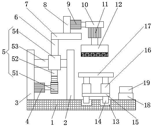
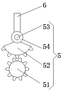
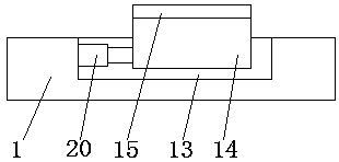
[0022] Such as Figure 1-3 As shown, the present invention provides a technical solution: a multi-angle grinding equipment for railway accessories, including a bottom plate 1, the upper surface of the bottom plate 1 is connected with the bottom end of the first fixed rod 2 and the bottom end of the second fixed rod 3 respectively Fixedly connected, the right side of the second fixed rod 3 is fixedly connected with the left side of the first motor 4 body, by se...


PUM


Abstract

The invention discloses equipment capable of grinding railway accessories in multiple angles. The equipment comprises a base plate, the upper surface of the base plate is fixedly connected to the bottom end of a first fixing rod and the bottom end of a second fixed rod, the right side surface of the second fixing rod is fixedly connected to the left side surface of a body of a first motor, and anoutput shaft of the first motor is fixedly connected to the left side surface of a rotating device. According to the equipment capable of grinding the railway accessories in multiple angles, by meansof the cooperation of the first motor, a second motor, a third motor, the rotating device, first electric push rods and second electric push rods, a switch is operated to enable the first motor to rotate, when a placing plate corresponds to a grinding block, the railway accessories can be ground, then the grinding block can grind the railway accessories in multiple angles, so that people do not need to manually adjust the positions of the railway accessories, the waste of physical power of people can be reduced, the effect of grinding the railway accessories can be better, and therefore the working efficiency of people can be guaranteed.

Description

technical field [0001] The invention relates to the technical field of railway equipment, in particular to equipment capable of grinding railway accessories from multiple angles. Background technique [0002] Railway accessories are an integral part of the railway line. The track referred to here includes steel rails, sleepers, connecting parts, ballast beds, anti-climbing equipment, rail supports and turnouts. As an integral engineering structure, the track is laid on the subgrade, plays a guiding role in the operation of the train, and directly bears the huge pressure of the rolling stock and its load. Under the power of the train running, its various components must have sufficient strength and stability to ensure the safe, stable and uninterrupted operation of the train at the specified maximum speed. [0003] When the traditional grinding equipment grinds the surface of railway fittings, because the flexibility of the device for grinding railway fittings is poor, the s...

Claims


Application Information

Patent Timeline
Patent Type & Authority Applications(China)
IPC IPC(8): B24B19/00B24B27/00B24B41/06B24B47/04
CPCB24B19/00B24B27/0015B24B27/0084B24B41/06B24B47/04
Inventor 李理
Owner 李理
Why Eureka
Try Eureka