Integrated robot joint device

An integrated technology of robot joints, applied in the direction of manipulators, manufacturing tools, joints, etc., can solve the problems of low load capacity, large size space, and short service life of harmonic reducers, so as to ensure high-quality stable operation and safe development Effect

Active Publication Date: 2018-06-29
BEIJING RES INST OF PRECISE MECHATRONICS CONTROLS
View PDF8 Cites 11 Cited by
  • Summary
  • Abstract
  • Description
  • Claims
  • Application Information

AI Technical Summary

Problems solved by technology

[0002] At present, most robot joints adopt a series independent structure scheme, that is, the motor, reducer and driver are independently designed and selected, and then connected to a complete machine device through an adapter device. This device has complex structural connections, large size space, and sub-components. The compatibility is not high, the comprehensive cost of man-hours and quality is relatively high, etc.
In this context, integrated design has become an inevitable trend. At present, most of the integrated joints of robots are designed on the basis of harmonic reducers. This device has low bearing capacity, low structural rigidity, and short service life of the harmonic reducer. Inherent problems, it is difficult to meet the needs of robots over 10KG

Method used


Image

  • Integrated robot joint device
  • Integrated robot joint device
  • Integrated robot joint device

Examples


Embodiment Construction

[0021] The present invention will be described in detail below in conjunction with the accompanying drawings and examples.

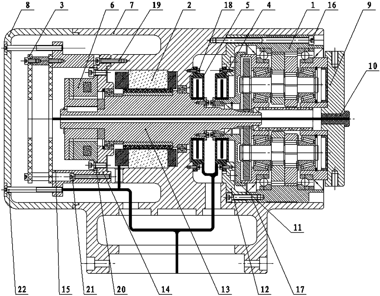
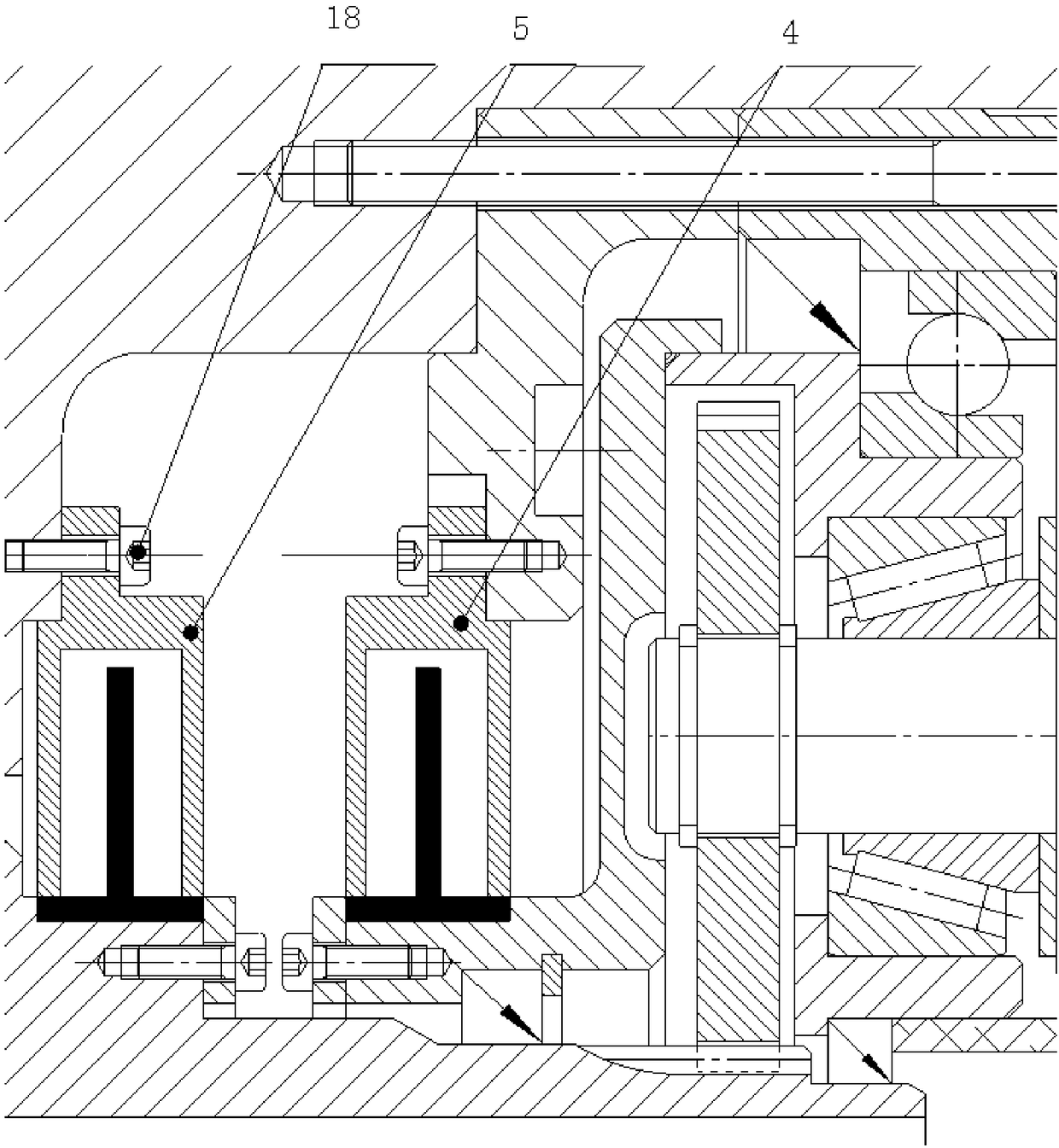
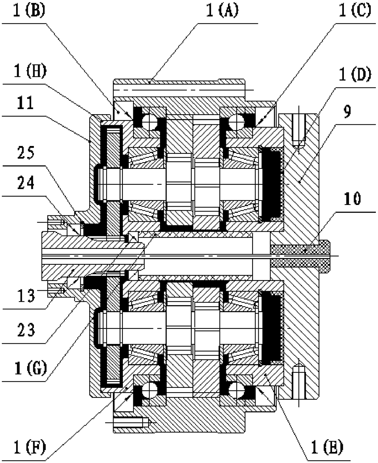
[0022] Such as figure 1 , 2 As shown, an integrated robot joint device includes RV reducer 1, frameless direct drive torque motor 2, DC drive 3, power-off brake 6, incremental encoder 5, single-turn absolute encoder 4, T Type shell 7;

[0023] The motor output shaft 13 is also used as the input shaft of the RV reducer; firstly, the motor incremental encoder 5 stator is fixedly connected to the inner end surface of the T-shaped housing 7 through the sensor connecting screw 18, and the rotor is installed on the motor output shaft 13, Thereafter, the stator of the frameless direct drive torque motor 2 is interference-fitted into the T-shaped housing 7 motor mounting seat, and its rotor is mounted on the motor output shaft 13 (specifically, it can be glued together), and then Install the motor output shaft 13 assembly on the T-shaped housing 7 through sup...


PUM


Abstract

The invention discloses an integrated robot joint device. The device is characterized in that a motor output shaft serves as an input shaft of a RV speed reducer; a rotor of a single-ring absolute value encoder is fixedly connected to an input end plate of the RV speed reducer through a sensor adapter plate, and a stator of the single-ring absolute value encoder is fixedly connected to a RV speedreducer shell through a sensor fixing plate; the rotor of an incremental encoder is fixed with the output shaft of the motor, and the stator of the incremental encoder is fixed to a T-shaped shell; the rotor of a frameless direct-drive torque motor is fixedly connected with the motor output shaft, and the stator of the frameless direct-drive torque motor is fixedly connected with the T-shaped shell; the rotor of a power-off type brake is connected with the motor output shaft, and the stator of the power-off type brake is fixedly connected with a motor end cover; a direct-current driver is connected to the T-shaped shell through a driver support, wherein the direct-current driver and the power-off type brake are arranged on one side of the frameless direct-drive torque motor, and the side is sealed by a rear sealing end cover; the RV speed reducer, the incremental encoder, the single-ring absolute value encoder are located on the other side of the frameless direct-drive torque motor; and an output flange is arranged on an output end plate of the RV speed reducer in a sealing manner.

Description

technical field [0001] The invention relates to a structural device for robot joints, which is mainly used to solve the problems of complex connection, large size and space, high cost and the like of the current robot joints. Background technique [0002] At present, most robot joints adopt a series independent structure scheme, that is, the motor, reducer and driver are independently designed and selected, and then connected to a complete machine device through an adapter device. This device has complex structural connections, large size space, and sub-components. The matching is not high, and the comprehensive cost of man-hours and quality is relatively high. In this context, integrated design has become an inevitable trend. At present, most of the integrated joints of robots are designed on the basis of harmonic reducers. This device has low bearing capacity, low structural rigidity, and short service life of the harmonic reducer. Inherent problems, it is difficult to me...

Claims


Application Information

Patent Timeline
Patent Type & Authority Applications(China)
IPC IPC(8): B25J17/02
CPCB25J17/0258
Inventor 侍威郑继贵罗智文郭喜彬
Owner BEIJING RES INST OF PRECISE MECHATRONICS CONTROLS
Why Eureka
Try Eureka