Breach intercepting stop lever device and breach plugging method

A technology of retaining rods and lifting devices, which is applied in water conservancy projects, embankments, sea area projects, etc., and can solve problems such as difficult, flexible and diverse crevasse sizes and crevasse depths, etc.

Inactive Publication Date: 2018-06-29
郑州玄一机器人有限公司
View PDF6 Cites 0 Cited by
  • Summary
  • Abstract
  • Description
  • Claims
  • Application Information

AI Technical Summary

Problems solved by technology

[0003] The above technology does not take into account flexible and diverse crevice sizes and crevice depths, and it is difficult to use

Method used


Image

  • Breach intercepting stop lever device and breach plugging method
  • Breach intercepting stop lever device and breach plugging method
  • Breach intercepting stop lever device and breach plugging method

Examples


Embodiment example 1

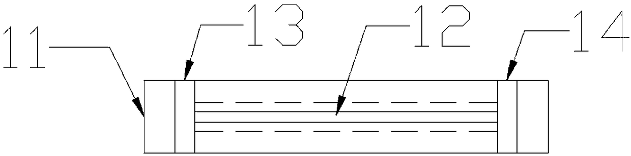
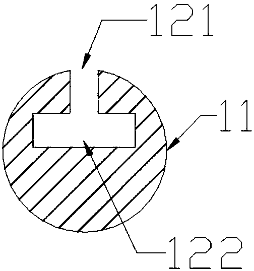
[0115] figure 1 It is a top view of a basic rod according to an embodiment of the present invention, figure 2 for figure 1 Sectional view of the foundation rod shown.

[0116] The basic rod 1 includes: the basic rod main body 11, more than one basic rod slideway 12 (including the top of the slideway 121, the inner part of the slideway 122), the limiting part of the basic rod slideway (including the front limiting part 13 of the basic rod slideway and / or Or the rear limiting part 14) of the basic bar slideway;

[0117] The basic rod main body 11 is a rod-shaped object, and the shape of its cross section includes at least one of circular, square, irregular shapes, etc. The diameter of the circumscribed circle of its cross section is more than 5 mm, and the length is more than 0.5 meters; preferably , the cross-section of the basic rod main body 11 is circular, the diameter of the cross-section is 60 mm, and the length is 3 meters.

[0118] More than one basic rod slideway 1...

Embodiment example 2

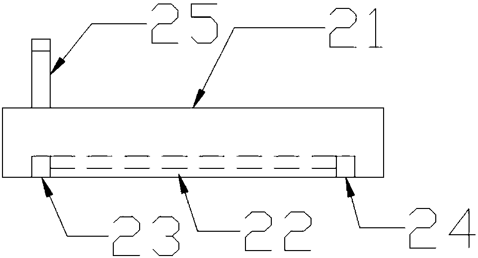
[0138] image 3 is a side view of the unit bar of another embodiment of the present invention, Figure 4 yes image 3 Shown is a cross-sectional view of a unit rod sliding part of a unit rod according to an embodiment of the present invention.

[0139] Unit bar 2 comprises: unit bar main body 21, more than one unit bar slideway 22, unit bar slideway limiting part (comprising unit bar slideway front limiting part 23 and unit bar slideway rear limiting part 24), more than one Unit rod sliding part 25;

[0140] The unit rod main body 21 is a rod-shaped object, and the shape of its cross-section includes at least one of circular, square, irregular shapes, etc., and the diameter of the circumscribed circle of its cross-section is more than 5 millimeters, and the length is more than 0.5 meters; preferred , the shape of the cross-section of the unit rod main body 21 is circular, the diameter of the cross-section is 60 mm, and the length is 3 meters;

[0141] The unit rod main bod...

Embodiment example 3

[0159] Figure 5 is a side view of the tail boom of another embodiment of the present invention.

[0160] The tail boom 3 includes: a tail boom main body 31 and more than one tail boom sliding part 35 .

[0161] The tail rod main body 31 is a rod, and the shape of its cross section includes at least one of circular, square, irregular shapes, etc., the diameter of the circumscribed circle of its cross section is more than 5 mm, and the length is more than 0.5 meters; preferably , the outer diameter of tail rod main body 31 is 60 millimeters, and length is 3 meters.

[0162] The tail rod sliding part 35 is located on the tail rod main body; the tail rod sliding part 35 is set in cooperation with the unit rod slideway 22, so that the tail rod 3 can slide on the unit rod slideway 22; the tail rod sliding part 35 cooperates fixedly arranged at the rear end of the tail rod 3;

[0163] Preferably, the relative position, size, structure, and number of the tail rod sliding part 35 a...


PUM


Abstract

The invention relates to a breach intercepting stop lever device and a breach plugging method. The breach intercepting stop lever device comprises a floating platform, a breach intercepting stop levergroup and a rotating device and can move on a water surface. The breach intercepting stop lever group is loaded on the breach intercepting stop lever device and comprises a plurality of stop levers capable of retracting and extending, the extending stop levers form a row of stop levers and can be fixed into silt at a water bottom, the folded stop levers occupy less space and are fixedly mounted,and unplanned extension of the breach intercepting stop lever group can be stopped. According to the breach plugging method, all the breach intercepting stop levers can form a group of stop levers inwater, the stop lever group is positioned in front of a dike breach and serves as a framework of a whole breach plugging operation, and then the breach is completely plugged by a conventional pluggingmethod. The breach plugging method is simple to operate, can rapidly response and can cope with different breach conditions.

Description

technical field [0001] The invention relates to a flood control device and a flood control method, in particular to a crevasse intercepting bar device and a crevasse sealing method. Background technique [0002] When rivers, lakes and dams burst, the disasters and economic losses caused are very serious. The currently used blocking technologies include "steel-wood-earth-rock composite dam" technology, reinforced cages, pebble bags, sandbags, stones and shipwrecks and other blocking methods. The work efficiency is low, the plugging time is long, and the cost is high. . In order to resist the disaster of the breach, people have developed various breach interception devices. The Chinese patent No. 200620072024.9 discloses a flood-fighting and rescue ship, which uses water-retaining tooth columns to gradually block the flood, which is convenient for operators to throw stones after the water speed decreases. material to block the breach. [0003] The above-mentioned technology...

Claims


Application Information

Patent Timeline
Patent Type & Authority Applications(China)
IPC IPC(8): E02B3/10
CPCE02B3/106Y02A10/11
Inventor 谢坚张黎燕石立公
Owner 郑州玄一机器人有限公司
Why Eureka
Try Eureka