Vertical spliced type underground diaphragm wall and construction method thereof

An underground diaphragm wall and construction method technology, applied in the direction of sheet pile walls, foundation structure engineering, construction, etc., can solve the problem of the overall rigidity of the diaphragm wall, the decline in deformation resistance, the inability of adjacent wall sections to leak water, and the weakening of reinforced concrete Stress conditions and other issues, to achieve the effect of good project implementation, low construction difficulty, and shorten the construction period

Inactive Publication Date: 2018-06-29
SHANGHAI INSTITUTE OF TECHNOLOGY
View PDF6 Cites 7 Cited by
  • Summary
  • Abstract
  • Description
  • Claims
  • Application Information

AI Technical Summary

Problems solved by technology

[0005] Chinese patent document 201610420302.3 discloses a "prefabricated assembled underground diaphragm wall structure". The underground diaphragm wall is spliced ​​by the cavity prefabricated components in the groove section through horizontal joints and vertical joints. When assembling, the horizontal joints are coated with waterproof glue, but There are still the following problems: (1) The large number of prefabricated bodies will lead to a large number of assemblies, but only one joint is set at its horizontal interface, which has an impact on the integrity of the continuous wall, and it may occur that adjacent wall sections cannot be aligned. and water leakage; (2) In the process of anchoring the joint bolts of vertical splicing, due to the lateral earth pressure, the construction is quite difficult; (3) The waterproof m

Method used


Image

  • Vertical spliced type underground diaphragm wall and construction method thereof
  • Vertical spliced type underground diaphragm wall and construction method thereof
  • Vertical spliced type underground diaphragm wall and construction method thereof

Examples


Example Embodiment

[0042] The present invention will be further described below in conjunction with specific embodiments and drawings to help understand the content of the present invention.
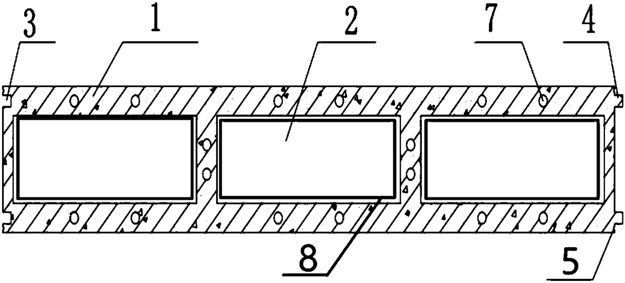
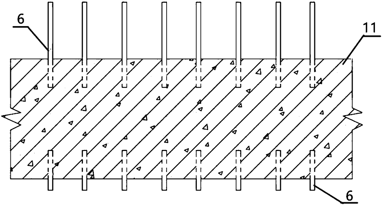
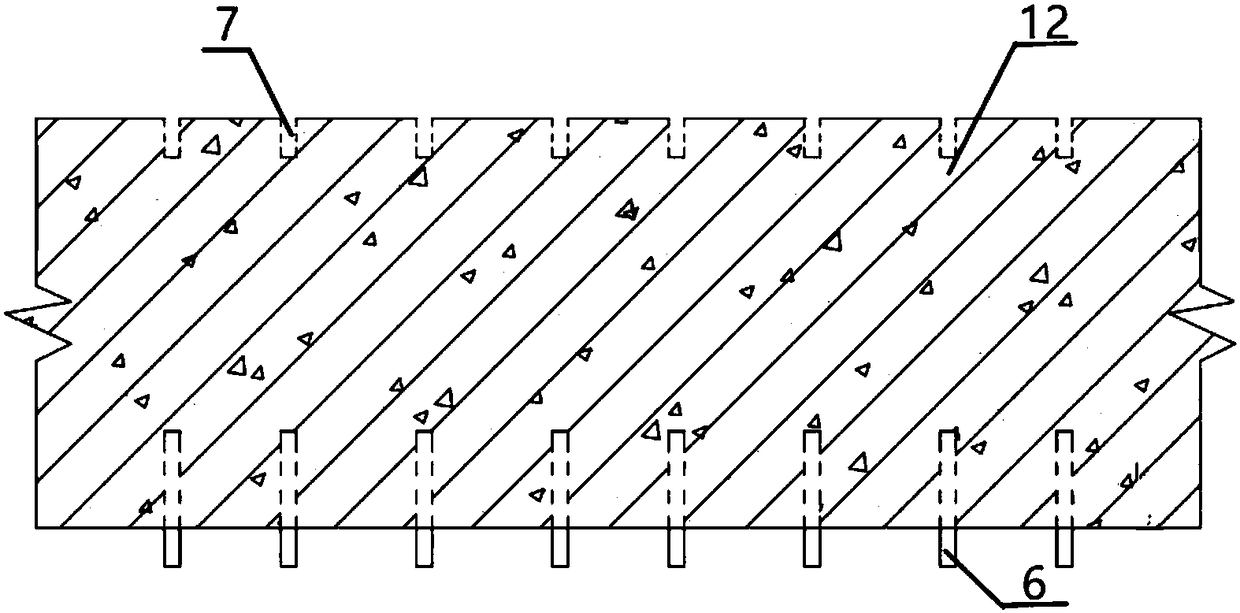
[0043] Such as Figure 1-6 As shown, a vertical splicing underground continuous wall provided by the present invention includes a continuous wall 1. Each segment of the continuous wall 1 is formed by at least three continuous wall units which are vertically spliced ​​together and divided from top to bottom. The upper continuous wall unit 11, the middle continuous wall unit 12, and the lower continuous wall unit 13 each have a length of 6m, a thickness of 1m, and a height of 10m. There are 3 upper and lower penetrations equally arranged inside. The cavity 2 of 50cm*150cm*1000cm is connected to the steel cage 8 inside the cavity. One end of each continuous wall unit is provided with a female port 3 recessed inward, and the other end is provided with a direction matching the female port 3. The convex male interf...


PUM


Abstract

The invention discloses a vertical spliced type underground diaphragm wall and a construction method thereof. The vertical spliced type underground diaphragm wall comprises diaphragm wall bodies 1. Each diaphragm wall body 1 is formed by splicing at least three diaphragm wall units in the vertical direction, wherein the diaphragm wall units are the upper layer diaphragm wall unit 11, the middle layer diaphragm wall unit 12 and the lower layer diaphragm wall unit 13 from top to bottom, the two sides of the top and bottom of the upper layer diaphragm wall unit 11 are each provided with six rebars 6, and two rebars are arranged between every two corresponding cavities 2; the top of the middle layer diaphragm wall unit 12 is provided with holes 7 matched with the rebars 6 at the top of the upper layer diaphragm wall unit 11, and the bottom of the middle layer diaphragm wall unit 12 is provided with a plurality of rebars 6; and the top of the lower layer diaphragm wall unit 13 is provided with holes matched with the rebars 6 at the bottom of the middle layer diaphragm wall unit 12. The two ends of each diaphragm wall unit are provided with a concave connector 3 and a convex connector 4correspondingly. According to the vertical spliced type underground diaphragm wall and the construction method thereof, continuous overall construction of the post-poured wall is achieved, and the overall mechanical compression resistance, tensile resistance and leak resistance are promoted substantially.

Description

technical field [0001] The invention belongs to the technical field of underground engineering, and in particular relates to a vertically spliced ​​underground continuous wall and a construction method thereof. Background technique [0002] Since the 21st century, with the rapid development of social economy, my country's subway has ushered in an unprecedented construction climax. By the end of 2016, the number of cities under construction in mainland China has increased to 53, with a total length of 4400km. As a common form of retaining wall for the main foundation pit enclosure of urban subways, the underground diaphragm wall has been widely used because of its reliable strength, high rigidity, and good integrity. [0003] At present, the underground diaphragm wall mainly adopts cast-in-place underground diaphragm wall and prefabricated underground diaphragm wall. Pour concrete. However, due to the technical characteristics of this underground diaphragm wall, the constru...

Claims


Application Information

Patent Timeline
IPC IPC(8): E02D5/20E02D5/10E02D5/12E02D5/14
CPCE02D5/10E02D5/12E02D5/14E02D5/20E02D2600/20
Inventor 李围申鹏程道来段景川张涛杨永杰秦海东张梦恒张华北许磊
Owner SHANGHAI INSTITUTE OF TECHNOLOGY
Why Eureka
Try Eureka