Self-partitioning pressure-superposed water supply system for high-rise building and water supply method

A superimposed water supply and self-zoning technology, applied in water supply pipeline systems, water supply devices, water supply main pipelines, etc., can solve the problems of low working efficiency, energy waste, power consumption and other problems of secondary pressure equipment, so as to improve water supply efficiency, The effect of reducing power consumption and reducing equipment wear and tear

Pending Publication Date: 2018-06-29
王丽
View PDF0 Cites 3 Cited by
  • Summary
  • Abstract
  • Description
  • Claims
  • Application Information

AI Technical Summary

Problems solved by technology

Both methods can supply water to middle and high-rise buildings, but the overall work efficiency of the secondary pressurization equipment is low. While meeting the water demand of middle and high-rise buildings, a large amount of electric energy is consumed, resulting in a great waste of energy

Method used


Image

  • Self-partitioning pressure-superposed water supply system for high-rise building and water supply method
  • Self-partitioning pressure-superposed water supply system for high-rise building and water supply method
  • Self-partitioning pressure-superposed water supply system for high-rise building and water supply method

Examples


Embodiment 1

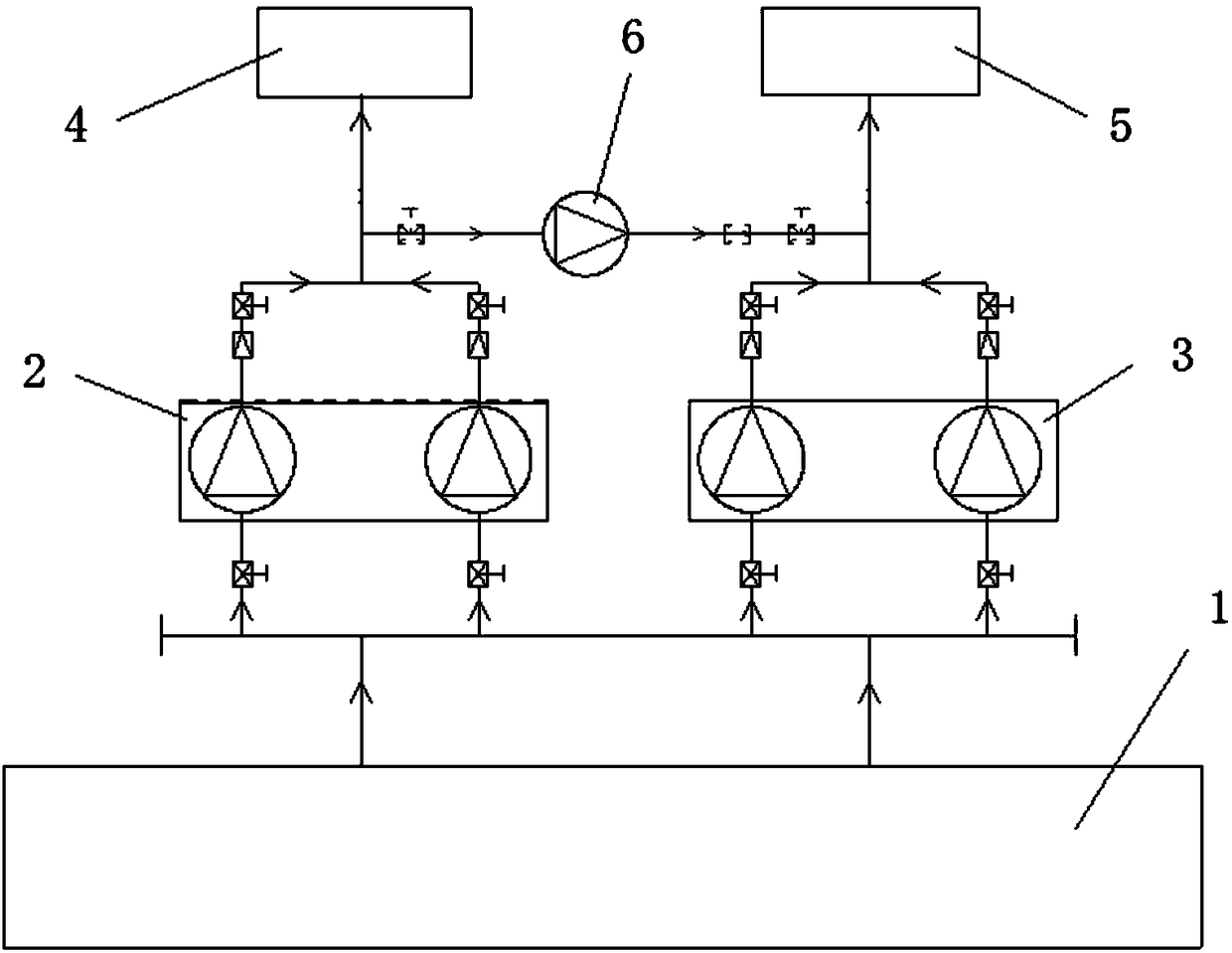
[0036] like figure 1 As shown, a building has a total of 14 floors, and the specific implementation steps are as follows:

[0037] (1) High-rise buildings are divided into low-pressure zone 4 (1-9 floors) and high-pressure zone 5 (10-14 floors) according to the floor height. Wherein, the low pressure area 4 is equipped with water pump group 1 2, and the high pressure area 5 is equipped with water pump group 2 3, and their water inlets are all connected to the water storage tank 1; Small flow water pump-6.

[0038] (2) In the low peak period of water consumption, the water pump group 23 is closed, the water pump group 12 and the small flow pump 16 are turned on, the water supply of the low pressure area 4 is provided by the water pump group 12; the water supply of the high pressure area 5 is sucked by the small flow water pump 16 1.2 The water on the water outlet side is provided after superimposing its water supply pressure.

[0039] (3) During the peak period of water cons...

Embodiment 2

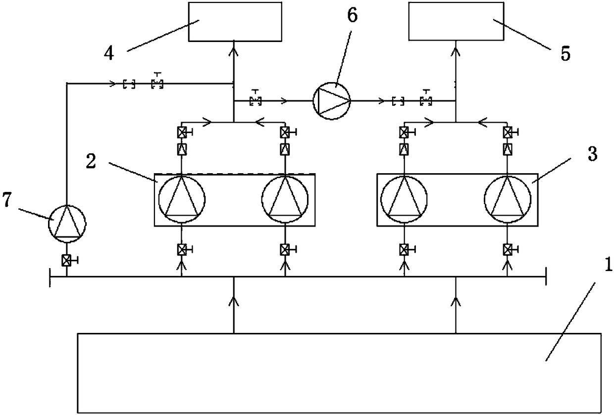
[0043] like figure 2 As shown, the difference from Embodiment 1 is that the outlet side of the water storage tank 1 and the water pump group one 2 is connected to the pipeline through the small flow water pump four 7, and in the low peak period of water use, the water pump group one 2 and the water pump group two 3 Closed, small flow pump 1 6 and small flow pump 4 7 are turned on, low-pressure area 4 is supplied by small-flow pump 4 7; high-pressure area 5 is supplied by small-flow pump 1 6 to absorb water from the outlet side of small-flow pump 4 7 and overlap Its water supply pressure is provided later, and the power saving effect is further improved.

Embodiment 3

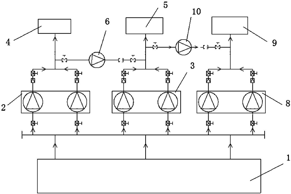
[0045] like image 3 As shown, a business hotel has a total of 28 floors, and the specific implementation steps are as follows:

[0046] (1) Divide high-rise buildings into low-voltage zone 4 (1-9 floors), high-voltage zone 5 (10-19 floors), and high-voltage zone 9 (20-28 floors) according to the floor level. Wherein, low-pressure zone 4 is equipped with water pump group one 2, high-pressure zone 5 is equipped with water pump group two 3, and high-pressure zone 9 is equipped with water pump group three 8, and their water inlets are all connected to water storage tank 1; A small flow water pump one 6 is equipped between the water outlets of the water pump group two 3; a small flow water pump three 10 is arranged between the water outlets of the water pump group two 3 and the water pump group three 8 outlets.

[0047] (2) During the low peak period of water consumption, the water pump group 2 3 and the water pump group 3 8 are closed, the water pump group 1 2, the small flow wa...


PUM


Abstract

The invention belongs to the water supply field and particularly relates to a self-partitioning pressure-superposed water supply system for a high-rise building and a water supply method. The technical scheme is as follows: the high-rise building is divided into a low-pressure region and a high-pressure region or a low-pressure region, a high-pressure region and a double-high-pressure region according to different water supply pressures required by floors with different heights; a water storage tank is in pipe connection with the low-pressure region through a water pump group I, is in pipe connection with the high-pressure region through a water pump group II and/or is in pipe connection with the double-high-pressure region through a water pump group III, effluent sides of the water pump group I and the water pump group II are in pipe connection through a small flow water pump I, effluent sides of the water pump group I and the water pump group III are in pipe connection through a small flow water pump II, and/or effluent sides of the water pump group II and the water pump group III are in pipe connection through a small flow water pump III. The self-partitioning pressure-superposed water supply system meets the water requirements of users of middle and high-rise buildings, meanwhile, the power consumption of the whole water supply system is reduced, the energy conservation andemission reduction purposes are achieved, and the water supply system can be widely applied to the construction and transformation of a water supply system for middle and high-rise buildings.

Description

technical field [0001] The invention belongs to the field of water supply, and in particular relates to a high-rise building self-partitioned superimposed water supply system and a water supply method. Background technique [0002] With the continuous increase of urban population, the scale of urban construction is gradually expanding, and there are row upon row of medium and high-rise buildings. Due to the limited water pressure of the municipal pipe network, the method of directly supplying water to users from the municipal pipe network used in the past by the city is only suitable for supplying water to low-level users, and cannot meet the water demand of middle and high-level users. Therefore, laying a secondary pressurization system on the basis of the existing municipal pipe network has become a commonly used water supply method for medium and high-rise buildings. [0003] my country mainly adopts two secondary pressurization methods of multi-zone frequency conversion...

Claims


Application Information

Patent Timeline
Patent Type & Authority Applications(China)
IPC IPC(8): E03B7/02E03B7/07E03B11/16
CPCE03B7/02E03B7/075E03B11/10
Inventor 王丽肖松
Owner 王丽
Why Eureka
Try Eureka