Bathroom frame and assembly method thereof
An assembly method and toilet technology, applied in special buildings, small buildings, building components, etc., can solve the problems of low efficiency of toilets, and achieve the effect of fast and efficient construction
- Summary
- Abstract
- Description
- Claims
- Application Information
AI Technical Summary
Problems solved by technology
Method used
Image
Examples
Embodiment 1
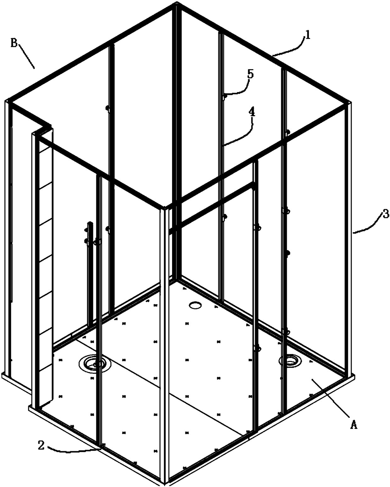
[0067] This embodiment provides a toilet frame, such as figure 1 As shown, including waterproof bottom box A and frame B. The frame includes a top frame 1 and a bottom frame 2, wherein the bottom frame 2 is formed by a bottom frame profile arranged along a circumference of the inner wall of the waterproof bottom box, which is a polygonal structure; the top frame 1 is connected with the bottom frame The bottom frame 2 is arranged opposite to the bottom frame 2, and is a polygon with the same shape as the bottom frame 2. The multiple corners of the top frame 1 and the multiple corners of the bottom frame 2 pass through a plurality of connecting beams in one-to-one correspondence. 3 connection, a plurality of the connecting beams 3 are arranged in parallel. Preferably, in order to be able to adjust the verticality and flatness of the wallboard when the wallboard is installed, the above toilet frame also includes a clamping beam 4, which is located between any two adjacent connec...
Embodiment 2
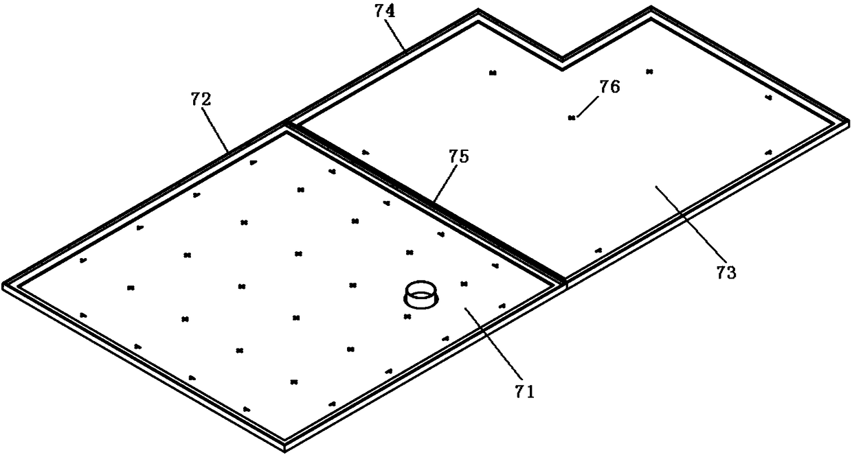
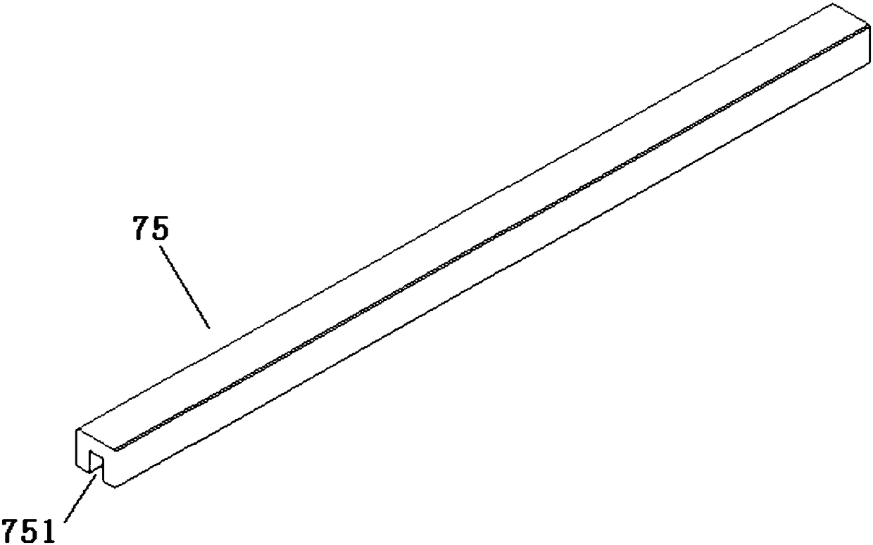
[0070] In this embodiment, the structure of the waterproof bottom box A is as follows Figure 2a As shown, it includes dry section, wet section, divider. Wherein, the surrounding edge 72 of the dry area is integrally formed with the ground 71 of the dry area, the surrounding edge 74 of the wet area is integrally formed with the bottom surface 73 of the wet area, and the dry area and the wet area are located on both sides of the partition bar 75 respectively. The surrounding part of the dry area and the adjacent part of the surrounding area of the wet area are used as the partition part of the partition part of the partition part of the dry part and the partition part of the partition part of the wet part, and the two are connected by the partition bar 75 . The structure of divider bar 75 is as Figure 2b As shown, it includes a surrounding edge slot 751 . The depth of the edge clamping groove 751 is adapted to the height of the edge 72 of the dry area and the edge 74 of th...
Embodiment 3
[0074] In the bathroom frame in this embodiment, the bottom frame profile structure adopted by the bottom frame 2 is as follows image 3 As shown, the bottom frame top chute 21 is molded on its upper surface.
[0075] In addition, the toilet frame also includes a bottom box connector 8, and the structure of the bottom box connector 8 is as follows: Figure 4 As shown, a square card slot 81 is formed thereon. to combine Image 6 , the partition end face of the dry area surrounding edge 72 and the partition end face of the wet area surrounding edge 74 are embedded in the square clamping groove 81; the outer walls on both sides of the square clamping groove 81 are respectively connected to the bottom The first profile and the second profile in the frame 2 are connected and fixedly connected, the first profile is the bottom frame profile located on the side of the edge partition of the dry area, and the second profile is located at the edge of the wet area. The bottom frame pro...
PUM
 Abstract
Description
Claims
Application Information
 - R&D
- Intellectual Property
- Life Sciences
- Materials
- Tech Scout
- Unparalleled Data Quality
- Higher Quality Content
- 60% Fewer Hallucinations
Browse by: Latest US Patents, China's latest patents, Technical Efficacy Thesaurus, Application Domain, Technology Topic, Popular Technical Reports.
© 2025 PatSnap. All rights reserved.Legal|Privacy policy|Modern Slavery Act Transparency Statement|Sitemap|About US| Contact US: help@patsnap.com


