Lubricating equipment for strip parts

A technology for lubricating equipment and parts, applied in mechanical equipment, engine lubrication, engine components, etc., can solve the problems of cumbersome coating process, poor moisturizing effect, uneven coating, etc., and achieves simple and compact structure, low manufacturing cost, and use easy effect

Active Publication Date: 2018-10-23
新沂市沙墩湖农业科技发展有限公司
View PDF6 Cites 0 Cited by
  • Summary
  • Abstract
  • Description
  • Claims
  • Application Information

AI Technical Summary

Problems solved by technology

[0002] For the lubrication of strip parts, lubricating oil is generally applied on the outer periphery of the strip parts, all of which are applied manually. Since the strip parts have a certain length, the application process is cumbersome and uneven, resulting in poor lubrication effect

Method used


Image

  • Lubricating equipment for strip parts
  • Lubricating equipment for strip parts

Examples


Embodiment Construction

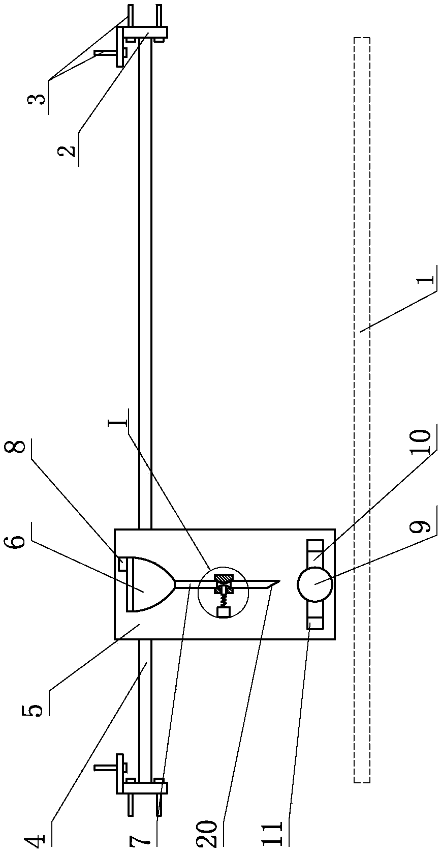
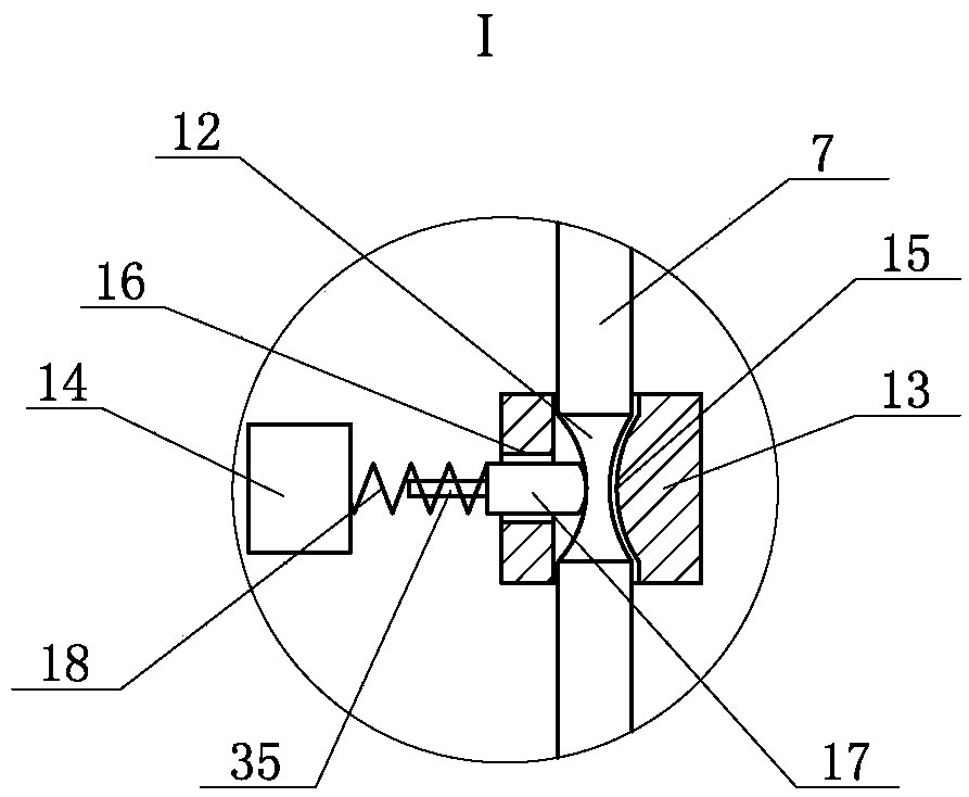
[0009] A kind of lubricating equipment for strip parts, such as figure 1 and figure 2 As shown, it includes a transverse guide rail 4, the transverse guide rail 4 is parallel to the bar-shaped part 1, the transverse guide rail 4 is located on the top of the bar-shaped part 1, and the horizontal guide rail 4 is provided with a movable seat 5 that can move horizontally, and an oil pot 6 is installed on the movable seat 5 , the top of the oil pot 6 is provided with vent holes 8, the lower end of the oil pot 6 is provided with a connected oil pipe 7, the bottom of the moving seat 5 is provided with a rotating disk 9 with a rotating motor, and connecting rods 10 are installed at the two ends of the rotating disk 9. An oil brush 11 is installed at the end, and the oil brush 11 can cooperate with the lower opening of the oil pipe 7; the middle part of the oil pipe 7 is a flexible pipe 12, and the middle part of the moving seat 5 is provided with a valve sleeve 13 and an electromagne...


PUM


Abstract

Lubricating equipment for a strip-shaped part comprises a transverse guide rail which is parallel to the strip-shaped part. The transverse guide rail is located above the strip-shaped part. A moving base capable of moving horizontally is arranged on the transverse guide rail. An oil can is arranged on the moving base. A ventilation hole is formed in the upper portion of the oil can. An oil pipe communicated with the oil can is arranged at the lower end of the oil can. A turnplate with a rotating motor is arranged on the lower portion of the moving base. Connecting rods are mounted at the two ends of the turnplate. Oil brushes are mounted at the ends of the connecting rods and can be matched with a lower opening of the oil pipe. A hose is located in the middle of the oil pipe. A valve sleeve and an electromagnet are arranged in the middle of the moving base. A vertical hole and a horizontal hole are formed in the valve sleeve and are identical to each other. The hose is located in the vertical hole, and a valve element is arranged in the horizontal hole. An iron core is arranged on the portion, outside the valve sleeve, of the valve element. The iron core can be matched with the electromagnet. A spring is arranged between the electromagnet and the valve element. According to the lubricating equipment, automatic operation is achieved; the consumption quantity of lubricating oil is extremely low in the lubricating process, but the whole lubricated part (the strip-shaped part) can be completely smeared with the lubricating oil during lubrication.

Description

technical field [0001] The invention belongs to the field of mechanical equipment, in particular to a lubricating equipment for strip-shaped parts. Background technique [0002] For the lubrication of strip parts, lubricating oil is generally applied on the outer periphery of the strip parts, all of which are applied manually. Since the strip parts have a certain length, the application process is cumbersome and uneven, resulting in poor lubrication effect. Contents of the invention [0003] In order to solve the above problems, the object of the present invention is to provide a lubricating device for strip parts. [0004] In order to achieve the above object, the present invention is achieved through the following technical solutions: a lubricating device for strip parts, including a transverse guide rail parallel to the bar parts, the transverse guide rail is located on the upper part of the bar parts, and a horizontally movable The mobile seat, the oil pot is installe...

Claims


Application Information

Patent Timeline
Patent Type & Authority Patents(China)
IPC IPC(8): F16N9/00
Inventor 牛传凯杨彪曲洋朱滨
Owner 新沂市沙墩湖农业科技发展有限公司
Why Eureka
Try Eureka